
Product Manual


7
Operating Instructions
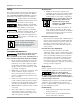
Oil Check
This unit is shipped with oil in it and should be
ready to operate. Be sure to check for proper oil
level before operating the compressor. Compressor
must be off at least 45 min. - 1 hr. before check-
ing to ensure accurate reading. Refer to figure 6.
Use only EMAX oil, model no.
AROL8000G1. For food
manufacturing applications, use model no.
AROLFOODG1. Use of any other product will cause
product damage and void the warranty. Refer to
warranty statement for oil requirements.
Electrical Installation
Be sure only trained and
authorized personnel install and
maintain this compressor in
accordance with all applicable
federal, state and local codes,
standards and regulations. Follow
all NEC (National Electric Code) standards especially
those concerning equipment grounding conductors.
1.
Follow all NEC and local codes for electrical wiring.
Allow only authorized EMAX service person or certi-
fied electrician to install electrical components.
2. Put unit on dedicated circuit and make sure
no other electrical equipment is wired into
it. Failure to wire unit on independent circuit
can cause circuit overload and/or imbalance
in motor phasing. Install proper No Fuse
Breaker (NFB) according to kW output of
compressor.
3. Ensure incoming service has adequate am-
pere rating.
4. Ensure supply line has the same electrical
characteristics (voltage, cycles and phase) as
the machine.
5. Refer to amp load information on motor tag
and use correctly sized wiring. Be sure to
consider distance between power supply and
machine.
6. Install surge protection device between power
supply and compressor electrical cabinet.
7. Make sure to install properly sized breakers and
fuses.
8. The unit must be properly grounded. DO NOT
connect ground wire to air or cooling lines.
Connect ground wire to grounding lug in the
compressor electrical cabinet.
Improperly grounded electrical
components are shock hazards.
Make sure all the components are
properly grounded to prevent
death or serious injury.
9. Make sure proper overload protection for the
motor is installed.
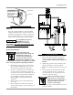
Figure 6: Sight Glass for Lubricating Oil
Oil level must be
maintained between
the two red lines
during operation and
while loaded
Air/Oil Tank
Sight Glass
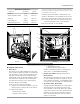
Figure 7: Wiring Diagram
A1
KM5
KM3
M1
PE
M
3
KM2 KM1 KM4
40
Inverter
Run
Main Motor
TB3
(Notice 2)
TB4
(Notice 2)
Inverter
Fault
37 22 14
PE E R
L1 L2 L3
S TCOM AI2
+24V LI1 U V WRIA RIC
L1
L1 L2 L3
L2 L3
B C
CT1
TB1
TB
QF
a
b
c
o
B C
CT2
a
b
c
o
M2
M
3
Fan Motor