
Pump Manual

4
Splash Lubricated, Air Compressor Pumps
3. If acid is used in operating environment
or air is dust laden, pipe intake to outside,
fresh air. Increase pipe size by one size for
every 20 feet of run. Be sure to install pro-
tective hood around intake filter.
4. In operating environments where excessive
water, oil, dirt, acid or alkaline fumes are
present, a TEFC (totally enclosed, fan cooled)
motor is recommended. Check nameplate for
motor type.
5. Allow sufficient space around compressor
pump for maintenance access. Mount unit
with pulley towards wall and leave a mini-
mum of 15 inches of clearance.
6. Use shims to level compressor if installation
area is not flat. This will avoid excessive
vibration and premature pump wear.
Piping
Safety Steps
1. Install appropriate flow-limiting valves as
necessary according to pipe size(s) used and
run lengths. This will reduce pressure in case
of hose failure, per OSHA Standard 29 CFR
1926.302(b)(7).
2. Flow-limiting valves are listed by pipe size
and rated CFM. Select appropriate valves
accordingly, in accordance with the manufac-
turer’s recommendations.
Tank Installation
1. Place tank feet
on 1/4” thick rubber pads.
Thicker padding will increase vibration and
the possibility of cracking the tank or other
unit damage.
Do not place unit on dirt floor
or uneven surface.
2. Fasten anchor bolts snugly but do not overtight-
en so normal vibration will not damage unit.
Compressor unit is top heavy and
must be bolted to solid, flat surface
to avoid falling and premature pump wear. Splash
lubrication will not operate properly if unit is not level.
Pump Installation
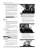
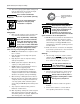
1. Mount pump to deck of tank then connect
main feed port to check valve in tank. See
figure 1.
2. For units with centrifugal unloader system,
install 1/4” copper tubing from 90˚ elbow
(located in front of crankcase) to the un-
loader port of check valve.
NOTE: If pump is not equipped with centrifugal
unloader, install an unloader line from the check
valve unloader port to the unloader port of the
pressure switch. This will relieve head pressure
when unit stops and provide no-load restarting.
3. Cap fitting on cylinder heads if not using
pilot valve for continuous run port.
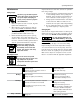
4. Make sure there is a 1/4” copper tube (un-
loader tube) installed from tank check valve
to unloader on pressure switch. This relieves
head pressure when compressor stops for
easier restart. See figure 2.
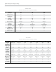
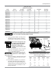
5. Use proper pulley for motor. Refer to Pulley
Size Chart for correct sizing.
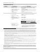
6. Install belts. There should be 1/2” slack for
proper belt tension. See figure 3.
7. Use a flexible connector between compressor
tank and piping system to minimize noise,
vibration, unit damage, and pump wear.
Figure 1: Connect feed port to check valve
Check
valve
Figure 2: Install unloader line from
check valve to pressure switch
Pressure switch
with unloader
Figure 3: Proper belt tension
1/2” deflection