
Pump Manual

5
Operating Instructions
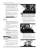
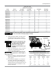
8. Install appropriate ASME code safety valves
and make sure piping system is equipped
with adequate condensate drains. See figure
4.
Never install a shut-off valve such
as a glove or gate valve, between
the pump discharge and the air
tank unless a safety valve is
installed in the line between valve
and pump.
9. Make sure any tube, pipe or hose connected
to the unit can withstand operating tem-
peratures and retain pressure.
Never use plastic (PVC) pipe for
compressed air. Serious injury or
death could result.
10. Never use reducers in discharge piping. Keep
all piping and fittings the same size in the
piping system.
11. For permanent installations of compressed
air systems, determine total length of sys-
tem and select correct pipe size. Make sure
underground lines are buried below frost line
and avoid areas where condensation could
build up and freeze.
Ball
Valve
Water Drain Valve
Air Tank
Air Dryer
Coalescing Filter
with Auto Drain
To Shop
Piping
Figure 4: Basic Piping Diagram
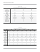
Minimum Pipe Size For Compressed Air Lines
(Pipe size shown in inches)
Length Of Piping System
SCFM 25 ft. 50 ft. 100 ft. 250 ft.
20 3/4 3/4 3/4 1
40 3/4 1 1 1
60 3/4 1 1 1
100 1 1 1 1-1/4
125 1-1/4 1-1/4 1-1/2 1-1/2
Pulley Size Chart
(Pulley size in inches)
Pump Electric 1750 RPM 3450 RPM Gas Engine Gas Engine
Model No. Motor - Hp 4 Pole Motor 2 Pole Motor Hp Pulley Size
APP2V0313S
3 5.5 2.75 5.5 3
APP3Y0518S
3 5.5 2.75 6.5 3
APP3Y0518S 5 5.75 2.75 6.5 3
APP3Y0521T 5 7 3.5 8 3.5
APP2V0732S
5 5.5 2.75 8 3
APP2I0524T
5 7.7 3.8 11 4
APP3Y0732T
5 6 3 11 3
APP3Y0732T 7.5 7 3.5 13 4
APP4V1043T
7.5 6.4 3.2 13 3.2
APP4V1043T
10 8.8 4.4 18 4.4
APP3Y1544T
10 9 4.5 24 4.5
APP3Y2062T
15 9 4.5 28 4.5
APP4V2598T
20 9 4.5 40 4.5
APP4V2598T
25 11.5 5.8 50 5.8
Splash lubricated pumps require 550 RPM for proper lubrication.
Be sure to size motor and engine pulleys correctly.