AIR DRYER Manual MODELS: EDR1150029 EDR1150050 EDR1150115 EDR1150130 EDR2300280 EDR4600280 EDR2300460 EDR4600460 EDR4600700 EDR4600850 EDR4601500 EDR4602000 07.08.13 Rev. 0.
AIR DRYER INSTRUCTION MANUAL Contents GENERAL SAFETY INFORMATION ....................................2 READ PRIOR TO STARTING THIS EQUIPMENT ...............3 DESCRIPTION..........................................................................3 INSTALLATION ......................................................................5 OPERATION .............................................................................7 MAINTENANCE ......................................................................
AIR DRYER INSTRUCTION MANUAL GENERAL SAFETY INFORMATION Safety This manual contains very important information on SAFETY and how to PREVENT EQUIPMENT PROBLEMS. The following will help in understanding this information: DANGER INDICATES AN IMMINENTLY HAZARDOUS SITUATION WHICH, IF NOT AVOIDED, WILL RESULT IN DEATH OR SERIOUS INJURY. WARNING indicates a potentially hazardous situation which, if not avoided, could result in death or serious injury.
AIR DRYER INSTRUCTION MANUAL READ PRIOR TO STARTING THIS EQUIPMENT 1. This equipment has been thoroughly checked, packed and inspected before leaving our plant. 2. This equipment is shipped to accommodate a forklift truck. Use a forklift when moving and installing this equipment. Never lift it by hooking on to the air inlet and outlet connections. 3. Clearances: Leave at least 24 inches or more (61 cm) on either side of the cabinet for free air flow.
AIR DRYER INSTRUCTION MANUAL Working Flow Compressed air, saturated with water vapor, enters the dryer and is pre-cooled by the outgoing refrigerated air in an air-to-air heat exchanger (pre-cooler). In the pre-cooler, the warm incoming air is precooled and the outgoing refrigerated air is warmed, this reduces the amount of heat that will have to be removed later by the refrigeration system, providing a more energy efficient dryer.
AIR DRYER INSTRUCTION MANUAL INSTALLATION Mounting 1. A dry, well-ventilated area is the best location for installation of the dryer. It also should be in an area where the ambient temperature will not exceed 100°F (38°C) or fall below 34°F (1°C). 2. A flexible hose should be added between the dryer and the air compressor in order to prevent stress to the inlet heat exchanger from the vibration of the compressor. 3. Mount dryer on firm level surface. 4.
AIR DRYER INSTRUCTION MANUAL Typical Piping connection Three-valve bypass line should be installed before the dryer air inlet valve and after the dryer air outlet valve. This valve always permits the continued use of the plant compressed air system during any dryer maintenance or servicing operations.
AIR DRYER INSTRUCTION MANUAL OPERATION Preparation for start-up 1. Be sure that voltage to unit, air inlet pressure, air inlet temperature, air flow is as marked on unit serial number tag. 2. Blow off the compressed air lines for a few minutes to remove welding slag. Start-up Checks: 1. Check the low refrigeration pressure gauge, it should indicate higher than 36 psi (0.25MPa). 2. Press the control button “ON” to start and make sure condenser fan is blowing air outward.
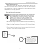
AIR DRYER INSTRUCTION MANUAL During Operation The current models use R134A refrigerant. Units with refrigeration dew-point gauges (models below 400 CFM), make sure reading is in the yellow and green area. If unit has a PLC (models 400 CFM & above), make sure the display shows 37oF (3 oC ). (Below 400 CFM units) DEW POINT READY . 37 ° F (400 CFM and above units) If dew-point temperature is below this range, the heat exchanger will freeze-up.
AIR DRYER INSTRUCTION MANUAL MAINTENANCE To avoid shock and serious personal injury, disconnect, tag and lock out power source then release all pressure from the system before attempting to install, service, relocate or perform ANY maintenance or troubleshooting. Air-cooled condenser Ambient air should be free to flow across the refrigeration condenser for heat exchanging. Do not locate the dryer in direct sunlight. Aircooled condenser should be cleaned with compressed air periodically.
AIR DRYER INSTRUCTION MANUAL FLOW SCHEMATIC 10
AIR DRYER INSTRUCTION MANUAL TROUBLESHOOTING Problem Dryer is switched on, indicator light is lit but the refrigerant compressor does not turn on.
AIR DRYER INSTRUCTION MANUAL TROUBLESHOOTING Problem Possible Cause Repair Dryer is switched on, indicator light is lit but the refrigerant compressor does not turn on. (Continued) Excessive temperature on crankcase of compressor. The hot gas bypass valve may be out of adjustment, faulty valve or low on refrigerant Allow time for compressor to cool. Check hot gas bypass adjustment and amount of refrigerant. Then reset refrigerant high pressure switch.
AIR DRYER INSTRUCTION MANUAL TROUBLESHOOTING Problem Possible Cause Dryer not running. No Power failure Power Faulty wiring, loose terminals Repair Check power to unit Request assistance from a qualified electrician or refrigeration contractor. Magnetic contactor Have contactor checked by damage a qualified electrician or refrigeration contractor & replace contactor if necessary Dryer-on light is lit Fan automatically runs Check amount of refrigerant. but fan is not running.
AIR DRYER INSTRUCTION MANUAL TROUBLESHOOTING Problem Possible Cause Condense pressure too High ambient high temperature Fan motor switch not set properly Air-cooled models – Dirty, clogged condenser fins, obstructed airflow across condenser Too much refrigerant Refrigeration system not functioning properly Repair Check minimum/maximum temperature ranges Set fan switch properly Clean condenser and check for good air flow Release excessive refrigerant Air in refrigerated cycle system Remove air in sys
AIR DRYER INSTRUCTION MANUAL TROUBLESHOOTING Problem Possible Cause Repair Comments Water in system Inlet and outlet connections are reversed. (compressed air) Check inlet and outlet connections. This dryer is designed for air flow in one direction only. Inlet and outlet directions are identified on the dryer. OUTLET INLET Drain system is clogged or inoperative. Bypass system is open Excessive air flow Free drain of obstructions, or repair drain, and make sure condensate water drains properly.
AIR DRYER INSTRUCTION MANUAL TROUBLESHOOTING Problem Possible Cause Repair Comments Water in system Excessive moisture in compressed air Check the separator and drain system and compressor after cooler ahead of the dryer. Excessive compressed air inlet temperature. Be sure that dryer is working lower than design conditions In some systems moisture accumulates in the line ahead of the dryer. If this moisture is pumped into the dryer intermittently, the water removal capacity may not be sufficient.
AIR DRYER INSTRUCTION MANUAL TROUBLESHOOTING Problem Possible Cause Repair High pressure drop Excessive compressed air flow or too low air inlet pressure. This dryer is designed for a maximum air flow. If too much air is pumped into the dryer, water removal capacity may not be sufficient, resulting in water carry-over downstream. Check the rated flow of the air compressor. Compressor room ambient is Frosting of the lines indicates the controls are set too low. above 41°F (5°C).
AIR DRYER INSTRUCTION MANUAL TROUBLESHOOTING Problem Possible Cause Repair Comments The dryer is designed for working into calculated design conditions, and if those conditions are exceeded, the dryer will be overworked, dew point goes up and protecting devices may trip. A high ambient temperature High ambient Designed conditions are may cause the refrigerant temperature described in dryer data plate.
AIR DRYER INSTRUCTION MANUAL WIRING DIAGRAMS All units are shipped with the wiring diagrams inside the units. The smaller units, the diagrams are attached to the inside of pull-off panel on the side of the electrical components. The diagrams for the larger units are on the inside of the electrical control box, which has to be removed with a Phillips-head screwdriver.