
Dryer Manual


AIR DRYER INSTRUCTION MANUAL
6
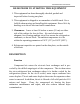
Typical Piping connection
Three-valve bypass line should be installed before the dryer air
inlet valve and after the dryer air outlet valve. This valve always permits
the continued use of the plant compressed air system during any dryer
maintenance or servicing operations.
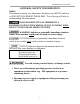
Power and electrical connections
TO PREVENT DEATH OR SERIOUS INJURY, ONLY TRAINED AND
AUTHORIZED PERSONNEL SHOULD INSTALL AND MAINTAIN
THIS COMPRESSOR IN ACCORDANCE WITH ALL APPLICABLE
FEDERAL, STATE AND LOCAL CODES, STANDARDS AND
REGULATIONS. FOLLOW ALL NEC (National Electric Code)
STANDARDS ESPECIALLY THOSE CONCERNING EQUIPMENT
GROUNDING CONDUCTORS.
1. Be sure that voltage to unit is as marked on unit serial number tag.
2. Range of voltage fluctuation will not exceed 10% of rated voltage.
3.
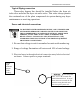
Electrical entry in through electrical connection entry hole in electrical
enclosure. Connect power to proper terminals.
Be sure the power
wires, L1, L2, & L3 match the
labeled terminal block. If any of
these wires are reversed, the fan
turns the wrong direction and
won’t keep the system cool.
Green
light
indicates
proper
phase
wirin
g
.