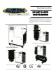
Operating Instructions ROTARY SCREW COMPRESSORS Polar Air designs and manufactures products for safe operation. However, operators and maintenance persons are responsible for maintaining safety. All safety precautions are included to provide a guideline for minimizing the possibility of accidents and property damage while equipment is in operation. Keep these instructions for reference. 08.29.13 Rev. 0.
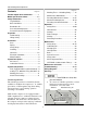
Polar Air Rotary Screw Compressors Contents Page No Page No Working Timer – Unloading Delay ......... 12 Variable Speed Drive Information .............. 1 Maintenance Notifications ...................... 13 Model Specification Charts ..................... 2-3 Resetting Maintenance Alarms .........13-15 Safety Information ....................................... 4 Mechanical Components ..................16-19 Tag Definitions .........................................
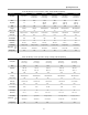
Operating Instructions Polar Air Rotary Screw Systems: 5 Hp - 20 Hp (VSD Compliant) Model No. PRS0070001 PRS0100001 PRS0070003 PRS0100003 PRS0150003 PRS0200003 Description Single Phase Single Phase Dual Voltage Three Phase Dual Voltage Three Phase Dual Voltage Three Phase Dual Voltage Three Phase Dual Voltage Motor 7.5HP 10HP 7.
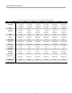
Polar Air Rotary Screw Compressors Polar Air Rotary Screw Systems: 75 Hp - 200 Hp (VSD Compliant) Model No.
Operating Instructions 3. Install, use and operate the compressor only in full compliance with all pertinent OSHA regulations and all applicable Federal, State & Local codes, standards and regulations. 4. NEVER modify the compressor and/or controls in any way. 5. Keep a first aid kit in a convenient place. Seek medical assistance promptly in case of injury. Avoid infection by caring for any small cuts and burns promptly.
Polar Air Rotary Screw Compressors 3. Use provided lifting feature or appropriate sling. A sling must be used when moving compressor with a helicopter or other airborne equipment. Be sure to follow OSHA standards 29 CFR 1910 Subpart N. 4. Use guide ropes or equivalent to prevent twisting or swinging of the compressor while it is in the air and NEVER attempt to lift in high winds. Keep compressor as low to the ground as possible. 5.
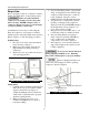
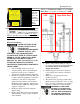
Operating Instructions Installation 2. Clearances around compressor. At least: 24 inches sides and back 3 feet in front of compressor. Area Exhaust air from this unit can be used to supplement environment heat. Install unit in separate room then create duct system as shown in figure 3. 1. Install compressor in a clean, well ventilated and well lit area. Make sure air inlet is away from exhaust fumes or other toxic, noxious or corrosive fumes or substances.
Polar Air Rotary Screw Compressors Ball Rotary 3. Install appropriate ASME code safety valves and adequate condensate drains on piping system. 4. Never use reducers in discharge piping. Keep all piping and fittings the same size in the piping system to help prevent pressure drops. 5. For permanent installations of compressed air systems, determine total length of system and select correct pipe size. Bury underground lines below frost line and avoid areas where condensation could build-up and freeze. 6.
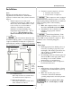
Operating Instructions Wiring for Variable Speed Drive or typical WyeDelta Start. See page 1 for advantages of VSD. Labels on tank show proper oil levels. Oil should be near bottom of sight tube when running. VSD Wye-Delta Start Figure 6: Sight Tube for Lubricating Oil Use only Polar Air oil, model no. Oil003. For food manufacturing applications, use model no. Oil001. Use of any other product will cause product damage and void the warranty. Refer to warranty statement for oil requirements.
Polar Air Rotary Screw Compressors Motor Rotation After electrical installation is complete, check the direction of the motor rotation. 1. Lightly push START and STOP buttons on the instrument panel. View unit while facing the drive pulleys (from the back). Check directional arrows on air end of pump 2. If motor shaft is not turning counterclockwise, disconnect power to terminal block then exchange any two of the three power leads.
Operating Instructions Setting:oC/ oF; BAR/PSI; Language; Time/Date 4. Now the current flashing gauge pressure setting, BAR (metric) or PSI (Am. Std) shows in display. Use the Up & Down arrows to change, if desired, and then press Enter to set the value. 1. Main screen starting point. Use to navigate through settings The Enter button used to navigate through settings 5. The current language setting now shows in the display.
Polar Air Rotary Screw Compressors 4. Arrow down to 0)WORKING PRESSURES and press Enter. Working Pressures These pressures settings are the compressor’s operating pressure settings, Top Range Transducer, High Pressure Alarm, Stop Pressure, etc. (See chart on page 13 of PLC manual.) 1. To access these settings, start with the main screen shown below. 5. WP1 (Top Range Transducer pressure) shows in the display. Press Enter and the pressure setting flashes and can be changed by using the Up & Down Arrows.
Operating Instructions Working Timer - Unloading Delay To reduce wear & tear of the compressor components, an unloading delay time is set in the controls that shuts-down the compressor after the unloading delay time has counted down. Enter in the 6 Digit Password 6 6 6 6 6 6, by using the Up Arrow to set the digit to 6 then press Enter to move to the next digit, and press the Up Arrow to set to 6, repeat until last digit is set to 6, then press Enter.
Polar Air Rotary Screw Compressors Following replacement times are important for safe operation. Remember to clear lifetime and reset maintenance timer after replacements are made. Refer to PLC manual for more details. 8. Enter in the 6 Digit Password 6 6 6 6 6 6, by using the Up Arrow to set the digit to 6 then press Enter to move to the next digit, and press the Up Arrow to set to 6, repeat until last digit is set to 6, then press Enter.
Operating Instructions Resetting Maintenance Alarms (Continued) 12. Press Down Arrow and CHANGE OIL FILTER shows in the display. Press Enter. 16. Press Down Arrow and CHANGE OIL FILTER shows in the display, but the first Line is C--=. This is the screen for the oil life. Press Enter. 13. Using Enter move over to NO and use the Up Arrow to change it to YES then press Enter and hours are reset. 17. Using Enter move over to NO and use the Up Arrow to change it to YES then hit Enter and it resets the hours.
Polar Air Rotary Screw Compressors 21. Using Enter move over to NO and use the Up Arrow to change it to YES then hit Enter and it resets the hours. Resetting Maintenance Alarms (Continued) 19. Using Enter move over to NO and use the Up Arrow to change it to YES then hit Enter and it resets the hours. Change to 4000 Change NO to YES Change NO to YES 22. After resetting the Bearing Lubricant timer, you can return to the Main Screen by Pressing the Down Arrow until you are back to the Main Screen. 20.
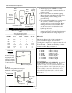
Operating Instructions Mechanical Components Side View End View Figure 9: Mechanical Systems Components Resetting Overload Protection 1. Drive Motor Drive motor is 4 pole with low RPM (1750). This motor is also capable of variable speed drive as a standard feature. The motor is 12 lead, Y delta soft starting for low amp draw. Overload protection is installed for safety.
Polar Air Rotary Screw Compressors A. Absorption The position and shape of the rotor shafts allow maximum air intake from the inlet port. As the shafts turn, the air is forced to move between the grooves of the screw threads. B. Sealing and Conveyance The air is sealed within the grooves of the screw threads and conveyed, or moved, through the machine casing toward the air outlet. C. Compression and Lubrication The rotor shaft screw threads are designed with decreasing space between the grooves.
Operating Instructions Mechanical Components (Continued) 7. Exhaust Probe (Continued) It is important to keep the circulating fan and cooler fins clean to prevent the compressor from shutting down. Low air pressure can be used to blow them off or if needed, use waterbased solvent to clean. 8. Oil Cooler The oil cooler function is to cool the hot oil from compressor pump and return oil to the air oil separator tank.
Polar Air Rotary Screw Compressors Mechanical Components (Continued) Operation 14. Check Valve (Continued) a) Actuates oil lubrication of the air end. b) Regulates air flow through the air separator filter to prevent damage to the separator filter element. Air flow begins when pressure in the air / oil separator tank reaches 43.5 PSI (3 bar). c) Prevents back flow from the air receiver tank into the air / oil separator tank. This component serves as a built-in check valve.
Operating Instructions Safety Rules (Continued) 9. Stop compressor and disconnect power if a hazardous condition arises. 10. Wear snug fitting clothing and confine long hair when around compressor. Keep all body parts and clothing away from couplings, fans and other moving parts of the equipment. 11. Keep hands, feet, floor controls and walking surfaces clean and dry. Initial Checks Be sure to make physical checks of the compressor to avoid serious failure before start-up. 1.
Polar Air Rotary Screw Compressors Storage 1. If the machine is stopped for over three weeks: a) Wrap electrical equipment such as the control panel with plastic or oil paper to avoid condensation. b) Completely drain water in the oil cooler, the back cooler and the oil/air separator tank. c) Make sure any unsafe conditions are clearly stated or repaired. 2. If the machine is not run for more than two months: a) Seal all ports to prevent moisture or dust accumulation.
Operating Instructions Compressor components can become hot during operation. Avoid bodily contact with hot liquids, hot surfaces and sharp edges and corners, or burns or personal injury could result. Safety Steps (Continued) 1. Make sure repairs are done in a clean, dry, well lighted and ventilated area. 2. When cleaning, use air pressure less than 30 psig (2.1bar). Also use effective chip guarding and personal protective equipment per OSHA standard 29 CFR 1910.242 (b). 3.
Polar Air Rotary Screw Compressors Air/Oil Separator Filter Use only Polar Air oil, model no.Oil003. For food manufacturing applications, use model no. Oil001. Use of any other product causes product damage and voids the warranty. Refer to warranty statement for oil requirements. Air/Oil Separator tank is a pressurized component. To avoid serious injury, be sure system pressure is relieved before removing filter. Be aware oil temperature may be very hot. Use caution when changing filter.
Maintenance Schedule Daily Weekly 500 hrs. 1000 hrs. 2000 hrs./ 6 months Check oil level Check coolant level Clean air filter Check belt tension Change lubricating oil (after first 500 hrs.
Polar Air Rotary Screw Compressors Troubleshooting Chart Problem Compressor will not start (Electric failure light is on) Possible Causes Resolutions 1. Power supply problem 1. Check complete circuit for proper voltage, ensure all electrical connections are secure; once power is restored, press Enter button on controls. 2. Blown circuit fuse and/or internal fuse 2. Replace fuse(s) as needed 3. Insufficient power to PLC 3. Check for correct voltage and make sure all fuses are functioning 4.
Operating Instructions Troubleshooting Chart Problem Compressor shuts down under compression mode/while loading (Continued) Possible Causes Resolutions 2. Loss of Control Voltage 2. Reset-Press Enter button on controls. If trouble persists, check line pressure does not exceed maximum operating pressure of the compressor (specified on nameplate) 3. Low incoming Voltage 3. 1. Air demand too high 1. Decrease air consumption or increase number of compressors in system 2. Blocked air filter 2.
Polar Air Rotary Screw Compressors Troubleshooting Chart Problem Possible Causes Line pressure exceeds upper preset safety limit (Continued) 5. High pressure shut-down preset is incorrectly programmed Resolutions 5. Reset to proper setting. Refer to PLC manual. 6. Additional compressor piped 6.
Operating Instructions Troubleshooting Chart Problem Excessive oil consumption (Continued) Pressure relief valve opens repeatedly AL02-Motor Overload Fault Possible Causes Resolutions 4. Oil level too high 4. Drain oil then check at sight glass for proper level 5. Lubrication system leak 5. Check all pipes, connections and components. Repair as needed 6. Low minimum pressure in separator tank 6. Minimum pressure should be 65 psi 1. High pressure shut-down preset is improperly programmed 1.
Polar Air Rotary Screw Compressors Troubleshooting Chart Problem Possible Causes Resolutions Excessive vibration 1. Loose component mounting 1. Inspect & tighten 2. Motor or compressor bearing failure 2. Replace bearing; Contact Eaton Compressor 3. External sources 3. Check for other sources of vibration, other than the compressor 4. V-belts slipping 4. Adjust belt tension or replace belts 5. Shipping brackets in place 5. Remove shipping brackets 1. V-belts loose 1. Adjusted belt tension 2.
Operating Instructions 30
Polar Air Rotary Screw Compressors 31
Operating Instructions 32
Polar Air Rotary Screw Compressors 33
Operating Instructions Warranty Statement EATON COMPRESSOR AND FABRICATION CO., INC. (and each of its subsidiaries, including POLAR AIR COMPRESSORS, INC.) makes the following Warranties: 1. THAT EACH ROTARY SCREW AIR COMPRESSOR PUMP TO BE FREE FROM DEFECTS IN MATERIAL, WORKMANSHIP, AND PARTS FOR 10 YEARS ON THE ROTARY SCREW AIR COMPRESSOR PUMP FROM THE DATE OF PURCHASE. Eaton Compressor and Fabrication Co., Inc. (and each of its subsidiaries) is not responsible for downtime during warranty service.