
Product Manual


Polar Air Rotary Screw Compressors
9
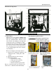
Motor Rotation
After electrical installation is complete, check
the direction of the motor rotation.
1. Lightly push START and STOP
buttons on the instrument panel. View
unit while facing the drive pulleys
(from the back). Check directional
arrows on air end of pump
2. If motor shaft is not turning counter-
clockwise, disconnect power to
terminal block then exchange any two
of the three power leads. Re-check
rotation.
System Description
The Polar Air compressor is highly efficient and
provides reliable performance with low wear
parts, low vibration and quiet operation. An
electric motor, which is controlled by a
Programmable Logistical Controller (PLC), runs
the compressor and is actuated with a belt drive
system. The belt drive system utilizes pulleys to
connect the motor to the main rotor shaft, or a
direct-drive coupling system.
Air Process
Air enters the system through the suction valve
which has an air/suction filter to remove dust. The
air is mixed with the lubricating oil and flows into
the air/oil separator tank. It passes through an
air/oil separator filter then through a minimum
pressure check valve. Air then passes through an
air cooled after cooler then into storage tank.
Lubrication Process
Pressure in the oil/air separator presses lubricating
oil into the oil cooler. The oil is cooled and
filtered then divided into two parts. One part is
injected into the compression chamber from the
lower end of the rotary compressor body to cool
the compressed air. The other part passes through
the two ends of the compressor body and is used
to lubricate internal roller bearings of rotary
compressor pump and gear drive. The two parts
meet at the bottom of the compression chamber
and are drained out with the compressed air.
System Components
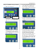
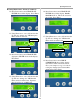
PLC (Programmable Logistical Controller)
The PLC is the compressor controller and has
a display screen for system information. The
electric circuitry of the PLC can be divided
into two systems. One is for the starting panel
to configure Y Delta starting. The other is for
internal computer controls and is explained in
more detail in the PLC manual. If there is any
failure, contact Polar Air service department.
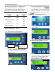
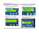
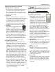
Refer to figure 8 for explanation of buttons.
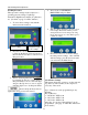
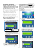
Maintenance Notifications
Six automatic maintenance notifications are
built into the Polar Air compressor system
designed to signify when maintenance is due
for certain components. The user is notified by
a message displayed on the control panel.
Refer to the following chart for the
components that have automatic maintenance
notifications and their factory set lifetimes.
1. ON Button: Press to start compressor
2. OFF Button:
Press to stop compressor
3. Emergency Stop:
Use only for emergency to stop
compressor immediately! Use normal stop at all
other times.
4. Enter/Confirm Button:
Press to enter a changed
setting or to confirm a menu selection.
5. Down Button:
Press to scroll down through menus
while changing settings or menu selections.
6. Up Button:
Press to scroll up through menus while
changing settings or menu selections.
Factory Set Passwords
: Level 1 = 22
Level 2 = 4444
Level 3 = 666666
1
2
3
456
Figure 8: PLC Control Buttons