
Product Manual


Polar Air Rotary Screw Compressors
17
Mechanical Components (Continued)
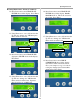
2. Variable Speed Drive (Energy saving device)
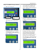
Ready Cabinet
This cabinet has allocated space and cooling
fan to house variable speed drive components.
To convert to Variable speed drive, contact
Polar Air customer service for more
information, 1-877-283-7614.
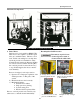
3. Air Suction Filter (Air Intake)
A dry type paper filter with filtra-
tion of 5 ppm, replace after first
600 hours of operation; then every 4000 hours,
depending on environment. Refer to the
computer controls of the compressor to
monitor operating time and reset maintenance
timer when filter is replaced. There is an
automatic alarm that can be set to remind
operator of service times.
4. Suction Valve
A butterfly valve that opens and closes during
operation. When PLC calls for air, the suction
valve opens through a solenoid valve to allow
compressor to load. When air pressure reaches
preset max level, the PLC closes the suction
valve allowing compressor to pull vacuum and
not compress air, or unload.
5. Regulation Modulation Control
This device is included on all 100-200 hp
models as an energy saving feature for
applications with duty cycles of 50% or
more. The device keeps amp load lower by
maintaining motor operation so consistent air
pressure is delivered under heavy workloads.
Units with lower duty cycles should use
online/offline (min./max. pressure) control.
Both control methods are available so
appropriate features can be selected for
different air demands. It is important to
monitor air demand since it takes 15% more
power to operate compressor for every10 PSI
of pressure increase
.
6. Air End
Two rotor shafts are mounted on bearings
parallel to each other in the machine casing.
The casing has an air inlet at the top and an air
outlet at the bottom. The shafts have precisely
machined, helical shaped screw threads which
work together to compress air. Air com-
pression occurs through a four course process:
A. Absorption
The position and shape of the rotor shafts
allow maximum air intake from the inlet
port. As the shafts turn, the air is forced to
move between the grooves of the screw
threads.
B. Sealing and Conveyance
The air is sealed within the grooves of the
screw threads and conveyed, or moved,
through the machine casing toward the air
outlet.
C. Compression and Lubrication
The rotor shaft screw threads are designed
with decreasing space between the
grooves. As air is moves through them, it
becomes pressurized and actuates the
lubrication process. Lubricating oil is
pressurized and injected into the
compression chamber during operation for
the following reasons:
a. To form protective film on rotors to
avoid contact and reduce friction.
b. To seal in the compressed air to
improve compressor efficiency.
c. To absorb heat to maintain optimal
power.
d. To reduce operating noise.
D. Exhaust
When the air has reached the end of the
rotor shafts, it is fully pressurized and
exhausted into the air tank. As the rotors
turn, the compression process continues.
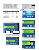
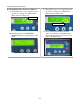
7. Exhaust Probe
The probe is temperature sensitive and located
at the air outlet of the rotary screw casing.
When exhaust temperature exceeds 210˚F
(98.8˚C), the system automatically powers
OFF. The temperature of the air exhaust can
be read on a display panel located on the PLC.
Common reasons for excessive exhaust
temperatures:
low oil level
inoperable exhaust fan
improper ventilation causing ambient air
temperature to be too hot
clogged oil filter
clogged radiator not allowing air-flow to
cool oil