
Product Manual


Polar Air Rotary Screw Compressors
7
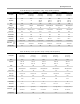
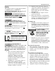
Minimum Pipe Size For Compressed Air
Lines
Pipe Size Shown in inches)
Length Of Piping System
SCFM 25 ft. 50 ft. 100 ft. 250 ft.
20 3/4 3/4 3/4 1
40 3/4 1 1 1
60 3/4 1 1 1
100 1 1 1 1-1/4
125 1-1/4 1-1/4 1-1/2 1-1/2
150 1-1/2 2 2 2
200 2 2 2 2
3. Install appropriate ASME code safety
valves and adequate condensate drains on
piping system.
4. Never use reducers in discharge piping.
Keep all piping and fittings the same size
in the piping system to help prevent
pressure drops.
5. For permanent installations of compressed
air systems, determine total length of
system and select correct pipe size. Bury
underground lines below frost line and
avoid areas where condensation could
build-up and freeze.
6. Test entire piping system before
underground lines are buried, and find and
repair all leaks before using compressor.
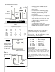
Oil Check
This unit is shipped with oil in it and ready to
operate. Check for proper oil level before
operating the compressor. Compressor must be off
at least 45 min. - 1 hr. before checking to ensure
accurate reading. Refer to figure 6.
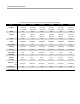
Oil Capacities:
7.5– 10 HP – 5 liters (1-1/3 gal)
15 – 20 HP – 6 liters (1-1/2 gal)
25 – 30 HP – 11 liters (3 gal)
40 – 60 HP – 20 liters (5-1/2 gal)
75 – 100 HP – 30 liters (8 gal)
125 – 150 HP – 70 liters (18 gal)
175 – 200 HP – 80 liters (21 gal)
DO NOT OVERFILL. Residual
oil may still be in the compressor. The above
capacities can be used for guidelines, but use the
upper arrow fill line on the sight glass (See page
7). Over filling causes oil to blowout the inlet
valve and through the air filter, also oil could
push past the separation system resulting in oil in
the air lines.
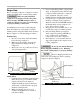
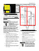
Rotary
Screw
Compressor
Cabinet
Air
Storage
Tank
Air
Dryer
Ball
Valve
Ball
Valve
To Shop
Piping
Water Drain Valve
Coalescing Filter
with Auto Drain
Figure 4: Basic Piping Diagram
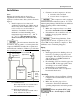
Figure 5: Closed Loop Installation
Air Drop
(typ.)
PLAN VIEW
Closed loop
system
Install tee fitting
in piping from air
supply to minimize
pressure drop and
to allow airflow in
two directions.
From Compressor
Air Drop
Install tee fitting with branch to top to
minimize condensation in air drop
ELEVATION
From
Com
p
resso
r
To Air Tool
Water trap
w/drain
Air Drop
(typ.)