MODULAR REGENERATIVE DRYERS USER/SERVICE MANUAL EMD US SERIES (EMD US-25 TO EMD US-260) WARRANTY NOTICE Failure to follow the instructions and procedures in this manual or misuse of this equipment will VOID its warranty !
TABLE OF CONTENTS SECTION 1—SAFETY 3 4 5 6 6 1.1 1.2 1.3 1.4 1.5 SECTION 5—STARTUP AND OPERATION SAFETY INFORMATION DEFINITION OF THE SAFETY SYMBOLS USED WARNINGS PROPER USE OF THE DRYER INSTRUCTIONS FOR THE USE OF PRESSURE EQUIPMENT 20 20 20 21 21 21 SECTION 2—INTRODUCTION 7 7 7 2.1 INTRODUCTION 2.2 GENERAL SPECIFICATIONS 2.3 PRESSURE SWING ADSORPTION (PSA) 22 5.1 INTIAL STARTUP 5.2 WITHOUT THE BY-PASS LINE 5.3 USING THE BY-PASS LINE 5.4 NORMAL OPERATION 5.
SECTION 1 SAFETY The dryer has been designed and constructed in accordance with the generally recognized rules pertaining to adsorption technology as well as industrial safety and accident prevention regulations. The equipment design, development, production, assembly and customer service fall under the Airbase quality control system.The dryer is state of the art.
1.2 DEFINITION OF THE SAFETY SYMBOLS USED Before attempting any intervention on the dryer, read carefully the instructions reported in this use and maintanance manual. General warning sign. Risk of danger or possibility of damage to the machine. Read carefully the text related to this sign. Electrical hazard. The relevant text outlines conditions which could result fatal. The related instructions must be strictly respected. Danger hazard. Part or system under pressure. Danger hazard.
1.3 WARNINGS Maintenance and/or control operation to be very carefully performed by qualified personnel 1. Compressed air inlet connection point. Compressed air outlet connection point. Condensate drain connection point. Operations which can be worked out by the operator of the machine, if qualified 1. In designing this unit a lot of care has been devoted to the protection of the environment: • Dryer and relevant packaging composed of recyclable materials. • Energy saving design.
1.4 PROPER USE OF THE DRYER This dryer has been designed, manufactured and tested only to be used to separate the humidity normally contained in compressed air. Any other use has to be considered improper. The Manufacturer will not be responsible for any problem arising from improper use; the user will be in any case responsible for any resulting damage.
SECTION 2 INTRODUCTION The EMD US range of compressed air dryers are designed to remove moisture from compressed air by utilising state of the art technology to obtain dewpoints of -40 (-40°F) PDP and by appropriate de-rating -70°C (-100°F) PDP. EMD US dryers have been designed to require minimal maintenance and can be installed virtually anywhere. The EMD US dryer consists of upper and lower head assemblies joined together with an aluminium extrusion containing twin internal chambers.
3.1 ESSENTIAL INFORMATION Care must be taken to ensure that the dryer is not subject to flows (even peaks) in excess of the dryers rated capacity, e.g. dryers downstream of an air receiver have increased potential to be overflowed. The dryer can be installed free standing, secured to the floor via the fastening points provided in the base or secured to a wall using optional brackets. The dryer must be installed vertical and level. Suitable rated pipe and connections must be used for the installation.
3.2 TECHNICAL SPECIFICATION Table 3-1: Operating Specification Parameter Minimum Maximum Nominal Inlet Pressure 60 psig (4.1barg) 230 psig (16.0 barg) 100 psig (6.9 barg) Control Air Pressure 60 psig (4.1barg) 145 psig (10 barg) 87 psig (6 barg) Ambient Air Temperature 34°F (1,6°C) 122°F (50°C) 100°F (38°C) Inlet Temperature 40°F (4.4°C) 120°F (48.
4.
4.
4.
4.
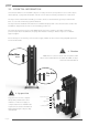
4.5 EMD US-25 ID TOP A 140 B C 10 M 330 A BACK B D C FRONT AIR INLET Model Type EMD US -25 Page 14 Inlet-Outlet Connection 1/2" B A C Length Width Height Weight mm Inc mm Inc mm Inc kg Ibs 350 13.8 370 14.5 1108 43.
4.6 EMD US-45-ID TOP A 190 B C 10 M 370 A BACK B D E C FRONT Model Type EMD US-45 Inlet-Outlet Connection 1 1/2" B A C Length Width Height Weight mm Inc mm Inc mm Inc kg Ibs 495 19.5 410 16.1 1250 49.
4.7 EMD US-110-120-ID TOP A B 260 130 C 370 BACK A B D E C FRONT Model Type Inlet-Outlet Connection B A C Length Width Height mm Page 16 Inc mm Inc mm Inc Weight kg Ibs Voltage EMD US-110 1 1/2" 622 24.5 430 22 1450 58 133 292 115-240V/50-60Hz EMD US-120 1 1/2" 622 24.5 430 25 1750 68.
4.
4.
4.
SECTION 5 STARTUP AND OPERATION 5.1 INITIAL STARTUP ıı Ensure a suitable supply of compressed air between 4,1 bar (60 psi g) and 16 bar (230 psi g) pressure is available and check that the dryer cannot be overflowed. IMPORTANT NOTE ıı ııı Control air pressure is to be below 10 bars. If the working pressure is above 10 bars then use a pressure regulator and set it below 10 bars. (Pressure regulator is not supplied with the dryer.) Inlet temperature must be between 4.
STARTUP AND OPERATION 5.4 NORMAL OPERATION Following the start-up procedure the operation of the dryer is fully automatic and requires no further attention until shut down. The green ‘power on’ LED and the green ‘correct operation’ LED should be illuminated continuously. The dryer contains two desiccant chambers, while one chamber is drying the compressed air (adsorption), The other chamber is simultaneously undergoing regeneration (desorption).
Page 22
SECTION 6 MAINTENANCE Maintenance operations should only be carried out by authorised personel 6.1 MAINTENANCE GUIDELINES • Maintenance operations should be held only when the system is shut down and fully depressurised ıı ııı • Do not modify or change the control setings • Use only approved replacement parts • Always check connections against leakage • Ensure all loose parts are removed and secured to the dryer before operation 6.2 DAILY CHECKS Functional and visual checks are to be done daily.
EMD US - 25 35 STAINLESS STEEL MESH 4 1 61 M-SSM-030 60 M-PPE-030 59 M-CRF-030 CORNER FITTINGS 2 58 M-NPL-030 NIPPLE 2 57 M-AOD-030 AIR OUTLET DISTRIBUTOR 1 1 2 PIPE 56 M-AID-030 AIR INLET DISTRIBUTOR 55 SEE.REF.
EMD US - 45 40 23 26 39 27 22 24 25 55 54 65 22 27 56 66 21 28 20 44 19 29 31 18 2 16 70 69 45 17 68 67 32 47 30 43 33 44 38 49 15 48 53 14 36 57 42 52 35 2 60 6 7 8 10 4 11 62 61 59 13 64 5 46 5 58 51 50 63 34 3 39 3 9 12 SHUTTLE VALVE MANIFOLD 1 40 72 73 71 41 SEAL KIT SEK-240 QTY. Ø122.00 Ø122.00 Ø3.00 M-1223 2 126.00 Ø3.00 M-6903 M-6403 Ø69.00 Ø3.00 1 1 Ø64.00 M-5203 Ø3.
SEAL KIT SEK-240 QTY. Ø122.00 EMD US - 110 Ø122.00 Ø3.00 M-1223 4 126.00 Ø3.00 M-6903 39 66 27 55 24 20 70 17 68 32 44 49 30 33 15 48 63 57 53 8 10 5 4 11 62 9 61 6 13 12 5 1 58 51 3 39 SHUTTLE VALVE MANIFOLD 40 43 71 MODEL EMD US 110 M-FRC-100 ITEM NO:43 59 42 7 2 46 60 50 72 73 2 Ø8.00 Ø2.00 2 Ø4.00 73 M-FTT-240 FITTINGS 3 72 M-RGT-240 REGULATOR 1 71 M-M4X20 BOLT 2 70 SEE.REF.TABLE PLATE 69 SEE.REF.
EMD US - 120 26 40 39 66 27 24 22 23 37 5 65 22 25 21 27 55 56 44 28 54 20 18 31 16 2 70 17 69 45 47 67 44 38 68 32 49 30 33 15 48 63 57 53 8 10 5 4 11 62 9 61 59 42 7 2 46 60 50 64 52 34 35 14 41 36 6 M-FTT-240 FITTINGS 3 72 M-RGT-240 REGULATOR 1 71 M-M4X20 BOLT 2 70 SEE.REF.TABLE PLATE 69 SEE.REF.
EMD US - 190 QTY. SEAL KIT SEK-240 26 40 5 Ø122.00 39 66 27 Ø122.00 Ø3.00 M-1223 6 126.00 23 37 24 22 22 25 5 65 21 56 55 54 M-5203 2 68 32 67 33 53 49 15 48 30 50 64 7 42 10 5 13 11 4 46 9 6 5 12 1 51 39 3 40 43 72 71 60 62 61 SHUTTLE VALVE MANIFOLD 59 Ø2.00 M-0802 Ø8.00 Ø2.00 M-0402 2 8 Ø4.
40 73 M-FTT-240 FITTINGS 3 72 M-RGT-240 REGULATOR 1 71 M-M4X20 BOLT 2 70 M-PLT-240 PLATE 1 69 M-CBS-240 CABLE SET 1 68 M-PSM-240 PLASTIC MESH 16 67 M-SSM-240 STAINLESS STEEL MESH 16 66 M-FTT-240 FITTINGS 2 65 M-NPP-240 NIPPLE 4 64 M-NPL-240 NIPPLE 2 63 M-TOW-240 TOWER 8 62 M-FSH-240 FUSE HOLDER 1 61 M-CCN-240 COUNTER CONNECTOR 1 60 M-STP-240 STOPPER 1 59 M-CBG-240 CABLE GLAND 2 58 M-CNT-240 CONNECTOR 1 57 M-BTC-240 BOTTOM COVER 1 56 M-GLD
TROUBLESHOOTING Problem Ind�cat�on Probable Cause Remedy Poor Dewpo�nt n/a H�gh �nlet temperature Check after cooler cond�t�on and clean as necessary Entra�ned Water Check pre-f�ltrat�on and pre-f�ltrat�on dra�ns Excess�ve a�r flow demand Check actual flow aga�nst rated flow of dryer Check for recent add�t�ons to a�r system Inlet pressure too low Check aga�nst techn�cal spec�f�cat�on Excess�ve �nlet a�r temperature Check aga�nst techn�cal spec�f�cat�on Insuff�c�ent purge a�r flow Factory se