
Product Brochure


Oper
ating
Instructions
7
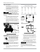
Not included
on all units
Pipe to tank outlet(s)
Manual OPEN/
CLOSE valve
Drain interval
Drain time
Filter access
Clean regularly,
see Fig 13.
Improperly grounded electrical
components are shock hazards.
Make sure all the components are
properly grounded to prevent
death or serious injury.
9.
Make sure proper overload protection for the
motor is installed.
Wiring Installation
Install power leads into terminals opposite motor
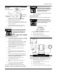
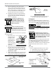
Figure 4: Auto Drain Feature
1.
Plug auto drain into 120V outlet.
2.
Set timers to desired settings. See figure 4.
If
drain is used for multiple units, increase
timer
settings as needed.
3.
Use test button to check proper operation.
Wires.
When wiring unit with magnetic
starter, do not install power
directly
to pressure switch to
avoid possible
fire and property
damage.
Refer to maintenance section for proper care.
Electrical Safety
Be sure only trained and
authorized
personnel install and maintain this
compressor in accordance with all
applicable federal, state and local
codes,
standards and regulations. Follow all NEC (National
Electric Code) standards especially those concerning
equipment grounding conductors.
1.
Follow all NEC and local codes for electrical wiring. Allow
only authorized EMAX service person or cer-
tified
electrician to install electrical components.
2.
Put unit on dedicated circuit and make sure
no
other
electrical equipment is wired into it. Failure to wire
unit on independent circuit can cause circuit
overload and/or imbalance in motor phasing. Install
proper No Fuse Breaker
(NFB) according to kW
output of compressor.
3.
Ensure incoming service has adequate ampere
rating.
4.
Ensure supply line has the same electrical char-
acteristics (voltage, cycles and phase) as the electric
motor.
5.
Refer to amp load information on motor tag and
use
correctly sized wiring.
Be sure to consider distance
between power supply and machine.
6.
Install surge protection device between power
supply and compressor motor.
7.
Make sure to install properly sized breakers and
fuses.
8.
The unit must be properly grounded. DO NOT
connect ground wire to air or cooling lines.
Ensure power supply and internal wiring is adequate
According to voltage and frequency stated on motor
nameplate and starter. Voltage should not vary more
than
12% to ensure proper operation of compressor.
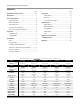
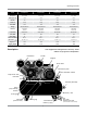
Wire Sizes
5hp – use #8 wire
7.5hp – use #6 wire
10hp – use #4 wire
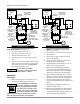
Single Phase Motors - No Magnetic Starter
1.
Connect first power lead to 1L1.
2.
Connect second power lead to 3L2.
3.
Connect ground wire to existing motor ground wire.
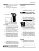
Figure 5: Single Phase Wiring Diagram
without magnetic starter
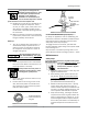
Single Phase Motors - With Magnetic Starter
1.
Connect first power lead to 1L1. Leave exist-
ing
jumper wire installed. See Figure 6.
2.
Connect second power lead to 3L2. Leave
existing
jumper wire installed.
3.
Connect ground wire to ground lug.
4.
Ensure all wiring and terminals are properly
tightened.
Br
eak
er
P
ower
Supply
220
V
P
ower
P
ower
1
2
1
2
3
4
M
otor
5
6
110V
Po
w
er
Wir
es
M
otor
Starter
Common
gr
ound
wire