
Use and Care Manual

6
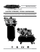
EMAX Electric Operated, Piston Compressors
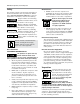
Piping / Tank Installation
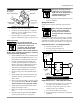
1. Place tank feet
on 1/4” thick rubber pads.
Thicker padding will increase vibration and
the possibility of cracking the tank or other
unit damage.
Do not place unit on dirt floor
or uneven surface.
2. Fasten anchor bolts snugly but do not overtight-
en so normal vibration will not damage unit.
Compressor unit is top heavy and
must be bolted to solid, flat
surface to avoid falling and premature pump wear.
Splash lubrication will not operate properly if unit
is not level.
3. Use a flexible connector between compressor
tank and piping system to minimize noise,
vibration, unit damage, and pump wear.
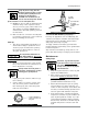
4. Install appropriate ASME code safety valves
and make sure piping system is equipped with
adequate condensate drains. See figure 2.
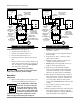
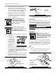
Refer to figure 3 for recommended closed loop
installation.
Never install a shut-off valve such as
a glove or gate valve, between the
pump discharge and the air tank
unless a safety valve is installed in
the line between valve and pump.
5. Make sure any tube, pipe or hose connected
to the unit can withstand operating tem-
peratures and retain pressure.
Never use plastic (PVC) pipe for
compressed air. Serious injury or
death could result.
6. Never use reducers in discharge piping. Keep
all piping and fittings the same size in the
piping system.
7. For permanent installations of compressed
air systems, determine total length of sys-
tem and select correct pipe size. Make sure
underground lines are buried below frost line
and avoid areas where condensation could
build up and freeze.
8. Test entire piping system before underground
lines are buried. Be sure to find and repair
all leaks before using compressor.
Never exceed recommended pressure
or speed while operating compressor.
Electronic Auto Drain (if equipped)
One auto drain can be used for multiple compres-
sor units. Install necessary piping with appropriate
fittings.
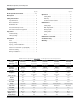
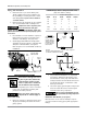
Minimum Pipe Size For Compressed Air Lines
(Pipe size shown in inches)
Length Of Piping System
SCFM 25 ft. 50 ft. 100 ft. 250 ft.
20 3/4 3/4 3/4 1
40 3/4 1 1 1
60 3/4 1 1 1
100 1 1 1 1-1/4
125 1-1/4 1-1/4 1-1/2 1-1/2
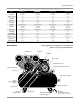
Ball
Valve
Water Drain Valve
Air Tank
Air Dryer
Coalescing Filter
with Auto Drain
To Shop
Piping
Figure 2: Basic Piping Diagram
Water trap
with drain
Air Drop
(typ.)
Air Drop:
Install tee fitting with branch to top
to minimize condensation in air drop
PLAN VIEW
Closed loop system
Install tee fitting
in piping from air
supply to minimize
pressure drop and
to allow airflow in
two directions.
ELEVATION
From
Compressor
From Compressor
To Air Tool
Figure 3: Closed Loop Installation