AOAA Kit – Software User’s Guide Copyright 2012 © Embedded Artists AB Android Open Accessory Application Kit Software User’s Guide Get Up-and-Running Quickly and Start Developing Your Application On Day 1! EA2-USG-1201 Rev A
AOAA Kit – Software User’s Guide Page 2 Embedded Artists AB Davidshallsgatan 16 211 45 Malmö Sweden info@EmbeddedArtists.com http://www.EmbeddedArtists.com Copyright 2012 © Embedded Artists AB. All rights reserved.
AOAA Kit – Software User’s Guide Page 3 Table of Contents 1 Document Revision History 5 2 Introduction 6 2.1 Demo Applications – Overview 6 2.2 Prerequisites 9 2.2.1 Software 9 2.2.2 Hardware 9 2.3 ESD Precaution 10 2.4 General Handling Care 10 2.5 Code Read Protection 10 2.6 Other Products from Embedded Artists 10 2.6.1 Design and Production Services 10 2.6.2 OEM / Education / QuickStart Boards and Kits 11 3 Demos 3.1 AOA Basic 12 3.1.1 Setup 12 3.1.
AOAA Kit – Software User’s Guide Page 4 5.2 The aoa_board_binaries_xxxxxx.zip 33 5.3 The aoa_can_node_xxxxxx.zip 33 5.4 The android_apps_xxxxxx.zip 33 5.5 The xpr_1769_bb_xbee_node_xxxxxx.zip 33 6 Modifying the Basic Demo 6.1 Add a New Message 35 6.1.1 Message Identifier in the Android App 35 6.1.2 Receive a New Message in the Android App 35 6.1.3 Send a New Message from the Android App 36 6.1.4 Message Identifier in the Accessory 37 6.1.
AOAA Kit – Software User’s Guide Page 5 1 Document Revision History Revision Date Description PA1 2012-02-27 First version.
AOAA Kit – Software User’s Guide Page 6 2 Introduction Thank you for buying The Android™ Open Accessory Application Kit from Embedded Artists. For the rest of the document the term Android Open Accessory will be written out as AOA. The kit (hardware and software) will be called The AOAA Kit, for short. When referring to just the hardware the term AOAA Board will be used. The kit has been developed by Embedded Artists in close cooperation with NXP.
AOAA Kit – Software User’s Guide Page 7 There are three AOA demo applications that can be downloaded from the Embedded Artists support page. The AOAA Board is not pre-loaded with any of these demo applications. The reason for this is that the applications are continuously updated and a pre-loaded application would quickly become outdated. This section gives an overview of the demos. For more information about how to work with the demos please read chapter 3 . The three AOA demo applications are: 1.
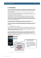
AOAA Kit – Software User’s Guide Page 8 All in all, there are applications on four separate devices. See picture below. 4) Wireless node (LPCXpresso Base Board or other AOAA board) RF 2) Android device RF 1) LPC1769 3) LPC11C24 Figure 2 – Applications Running in Parallel Up to three of them are running in parallel in the demo applications. 1) LPC1769 – this application runs on a fast ARM Cortex-M3 processor with up to 120MHz core frequency.
AOAA Kit – Software User’s Guide 2.2 Page 9 Prerequisites This section lists what is needed to get started with application development with the AOAA kit, i.e., with AOA experiments and prototyping. 2.2.1 Software The following software packages are needed to start working: 1) For program developing on the Accessory side (LPC1769 and LPC11C24), the latest version of the LPCXpresso IDE must be downloaded and installed. See [13] http://www.nxp.
AOAA Kit – Software User’s Guide Page 10 If a USB charger does not exist an external +5VDC/1A supply can be used. A standard 2.1mm power jack input exists on the board. Center pin is positive. 5) A USB cable to the Android device. Normally this is a USB-A (inserted in AOAA Board) to USB micro-B (inserted in Android device) cable, but not always. Some Android devices have special USB connectors. Use the cable that comes with the Android device and connect to the USB-A connector on the AOAA Board.
AOAA Kit – Software User’s Guide 2.6.2 Page 11 OEM / Education / QuickStart Boards and Kits Visit Embedded Artists’ home page, www.EmbeddedArtists.com, for information about other OEM / Education / QuickStart boards / kits or contact your local distributor.
AOAA Kit – Software User’s Guide Page 12 3 Demos 3.1 AOA Basic This demo shows how to send data in both directions between the AOAA Board and the Android device. The AOAA Board has two buttons; two RGB LEDs and a trimming potentiometer (see Figure 3).
AOAA Kit – Software User’s Guide Page 13 6) Connect the Android device to the AOAA Board as shown in Figure 3. 3.1.3 Running the Demo The first thing that happens as the Android device is connected to the AOAA Board is that a dialog appears asking “Open AOA Basic when this USB accessory is connected?” Answer OK to start the application. The Application will look like Figure 4 below. The buttons control the two RGB LEDs on the AOAA Board.
AOAA Kit – Software User’s Guide Page 14 CAN Node Powering of the board Connected to Android device Figure 6 - AOAA Board: CAN Demo The CAN node has a light sensor, a temperature sensor, a button, an RGB LED and a red LED. All are accessed in this demo. Note 1: As long as the CAN node is connected to the AOAA Board there is no way to test the plugand-play functionality of the CAN bus.
AOAA Kit – Software User’s Guide 3.2.1 Page 15 Setup This setup uses the prebuilt version of the AOA Node application (Android application) that is stored on the Embedded Artists’ web site. 1) Flash the demo_aoa_can project on the AOAA Board using the LPCXpresso IDE as explained in section 4.3 2) The CAN node has an LPC11C24 that come pre flashed with the correct software for this demo.
AOAA Kit – Software User’s Guide Page 16 Figure 10 - Accessory Disconnected 3.3 AOA XBee The AOAA Board has a connector for an XBee wireless module (see Figure 11). This demo shows how to use the AOAA Board as a gateway between the Android device and an XBee network.
AOAA Kit – Software User’s Guide Page 17 XBee Node running on an LPCXpresso Base Board XBee Node running on an AOAA Board Gateway for the XBee network – connected to Android device Figure 12 - XBee Demo Setup Note that at least two XBee modules are needed: one on the AOAA Board acting as a gateway and the second on the board acting as an XBee node. In Figure 12 there are three XBee modules since two XBee nodes are connected to the gateway. 3.3.
AOAA Kit – Software User’s Guide Page 18 Figure 13 – J7 Jumper Position for LPCXpresso Base Board 1) Flash the demo_aoa_xbee project on the AOAA Board using the LPCXpresso IDE as explained in section 4.3 2) Connect the LPCXpresso Base Board to the PC. 3) Follow the instruction in section 4.3 but download and use the xpr_1769_bb_xbee_node_xxxxxx.zip file for the code. 4) Connect the Android device to the AOAA Board as shown in Figure 12.
AOAA Kit – Software User’s Guide Figure 14 - List of detected XBee nodes Page 19 Figure 15 - Controlling XBee Node 1 Each discovered node sends its capabilities to the gateway which forwards the information to the Android application which in turn alters the user interface to reflect this. In Figure 15 there is no light sensor compared to Figure 9 even if it is the same application. The Android application detects when the USB cable is disconnected and changes the appearance to reflect this.
AOAA Kit – Software User’s Guide Page 20 3) The IP number for the AOAA Board is statically defined (i.e. no DHCP) and must likely be modified to avoid conflicts with the network it will be connected to. The IP address, net mask and gateway settings can be found in main.c. 4) Attach the network cable to the AOAA Board. 5) Flash the lwip_httpd project on the AOAA Board using the LPCXpresso IDE as explained in section 4.3 3.5.
AOAA Kit – Software User’s Guide Page 21 4 Guides 4.1 Installing Suggested Android Application When connecting the Android device to the AOAA Board the Android device searches for a matching application. If one cannot be found then a dialog appears as shown in Figure 16. Click the View alternative which will launch a web browser to download the file. The downloaded file is visible when the notification bar is expanded (see Figure 17). Install the application by clicking on it.
AOAA Kit – Software User’s Guide 4.2 Page 22 Setting up Android Projects This section describes how to compile the demo applications for the Android device. 1. The Android SDK with support for Android 2.3.4 (API 10) must be installed on the computer, see reference [5]. It is out of the scope of this document to describe how to install the SDK. 2. As the demo applications are based on Android 2.3.4 (API 10) an extra package is needed, see reference [4] 3. Start Eclipse in a new empty workspace. 4.
AOAA Kit – Software User’s Guide Page 23 Figure 21 - AOADemo in Eclipse editor 4.3 Setting up Projects in LPCXpresso This section describes how to compile the demo applications for the LPC1769 (the same applies for the LPC11C24), developed on the LPCXpresso IDE. There are introduction videos and presentations about how to get started with the LPCXpresso IDE on the LPCXpresso website, see reference [13]. 1) Make sure that the latest version of the LPCXpresso IDE is installed.
AOAA Kit – Software User’s Guide Page 24 1) Select Import and Export 2) Select Import archived projects (zip) Figure 22 – LPCXpresso IDE Import Archived Project 5) Browse and select the downloaded zip file containing the archived sample applications. Select all sub-projects to be imported, see Figure 23 below.
AOAA Kit – Software User’s Guide Page 25 6) By default the NXP USB library has been configured for USB device only. This needs to be changed to USB host. Right click on the nxpUSBlib project and select Build Configuration, then Set Active. In the list select LPC17xx_Host. See Figure 24. Figure 24 – Configuring nxpUSBlib for USB Host 7) The projects are now imported. Click (to select) the project to work with. 8) Click Build in the Quickstart Panel (under Start Here).
AOAA Kit – Software User’s Guide Page 26 1) Click (to select) project to build 2) Build/clean project Figure 25 – LPCXpresso IDE Build Project 4.4 Debugging a Project in LPCXpresso Before attempting to debug, the AOAA Board must be powered and the LPC-Link should be connected via the 10-pos flat cable. For instructions see sections 3.3 and 5.1.2 in the hardware user’s manual. To debug the demo application: 1) Select the project to work with 2) Click Debug in the Quickstart Panel (under Start Here).
AOAA Kit – Software User’s Guide Page 27 1) Click (to select) project to build 2) Debug project Figure 26 – LPCXpresso IDE Debug Project In case flashing fails, an error message like below will be displayed. This is an indication that the debugger could not connect to the LPC1769 or LPC11C24. The most common reason is that the microcontroller was in a low-power mode where debug connection is not possible. Make sure the microcontroller is in ISP/bootload mode and try again.
AOAA Kit – Software User’s Guide Page 28 2) Click the Debug as… button. See Figure 28 Click to start debugger Figure 28 - Start debugger 3) Select Android Application in the dialog that appears. See Figure 29 Figure 29 - Debugging type 4) The Android Device Chooser appears (see Figure 30). The connected Android device should be listed under Running Android devices. Select it and press OK. 5) The application will now be installed and started on the selected Android device.
AOAA Kit – Software User’s Guide Page 29 Figure 30 – Android Device Chooser 4.6 Preparing the Android Device Before attempting to debug the Android application the device must be prepared and connected to the PC: 1) The demo has not been uploaded to Android Market. In order to install the demo from a different source the settings in the Android device must be changed.
AOAA Kit – Software User’s Guide Page 30 Figure 32 - Unknown Sources - Motorola Xoom 2) One more setting that is useful when developing applications for an Android device is to enable USB debugging. Go to Settings, Applications, and then Development and enable USB debugging, see Figure 33 for Nexus One and Figure 34 for Motorola Xoom.
AOAA Kit – Software User’s Guide Page 31 Figure 34 - USB Debugging - Motorola Xoom 3) The device drivers for the Android device must be installed on the PC. See the user’s guide for the device on how to install the driver.
AOAA Kit – Software User’s Guide Page 32 5 Software packages A couple of zip files are available on Embedded Artists’ support pages. Register using the serial number accompanying the AOAA Board to gain access to the pages. The zip files (note that xxxxxx is the date that the package was created): 1) The aoa_board_xxxxxx.zip contains all the software needed for the LPC1769 on the AOAA Board. 2) The aoa_board_binaries_xxxxxx.zip contains pre-compiled versions of the demos in aoa_board_xxxxxx.zip.
AOAA Kit – Software User’s Guide Lib_FatFs_SD Page 33 Contains ChaN's Fat FS Module ported to the LPCXpresso Base Board. http://elm-chan.org/fsw/ff/00index_e.html Lib_FreeRTOS A port of FreeRTOS Lib_lwip A port of lwIP ver 1.4.0 Lib_MCU Drivers for the MCU peripherals nxpUSBLib NXP’s USB library 5.2 The aoa_board_binaries_xxxxxx.zip As the name suggests the aoa_board_binaries_xxxxxx.zip file contains pre-compiled versions (as *.hex files) of all the demos in aoa_board_xxxxxx.zip.
AOAA Kit – Software User’s Guide Page 34 need to unzip this file – instead use the procedure described in section 4.3 to open it in an LPCXpresso IDE workspace. The workspace will contain 4 projects: Project Description Lib_Board Board specific drivers shared by multiple projects. Includes e.g. Xbee, E2PROM and button code. Lib_CMSISv2p00_LPC17xx The CMSIS (Cortex Microcontroller Software Interface Standard) library.
AOAA Kit – Software User’s Guide Page 35 6 Modifying the Basic Demo This chapter describes how to modify the AOA Basic demo (see section 3.1 ) applications in order to add new messages being sent between the Android device and the accessory. Changes to the demo means modifying both the Demo_AOA_Basic Android application (referred to as Android App below) and the demo_aoa_basic project (referred to as Accessory below). 6.
AOAA Kit – Software User’s Guide Page 36 if (len >= 2) { Message m = Message.obtain(handler, AccessoryControl.MESSAGE_IN_BTN_1); m.arg1 = toInt((byte)0, buffer[pos + 1]); handler.sendMessage(m); } pos += 2; break; … The Handler which receives the message must also be modified to react on the message, which typically is to update something in the user interface. Open the MainActivity.java file and locate the instantiation of the Handler and add handling of the new message.
AOAA Kit – Software User’s Guide 6.1.4 Page 37 Message Identifier in the Accessory Add a new message identifier in the accessory by opening the AndroidAccessoryHost.c file and define a new constant with a unique ID. See how these defines are related to the constants in the AccessoryControl.
AOAA Kit – Software User’s Guide Page 38 data[0] = (v >> 8); data[1] = (v & 0xff); sendCommand(CMD_TRIMPOT, data, 2); } lastTrimpotCheck = getMsTicks(); } btn = btn_get(); btn1 = ((btn & BTN_SW2) != 0); btn2 = ((btn & BTN_SW3) != 0); if (lastBtn1State != btn1) { lastBtn1State = btn1; data[0] = btn1; sendCommand(CMD_BTN_1, data, 1); } Copyright 2012 © Embedded Artists AB
AOAA Kit – Software User’s Guide Page 39 7 CAN Demo – Protocol This chapter describes the proprietary protocol (below called EACAN) used in the CAN demo when sending messages over the CAN network. CAN network Node Controller Node Node Node Figure 35 – Example of EACAN network A CAN network consists of two or more CAN nodes, but on the EACAN network one of these nodes have been assigned the role of Controller while the rest are considered to be Nodes.
AOAA Kit – Software User’s Guide 7.2 Page 40 EACAN Format The EACAN format is described below and how it is associated with the CAN frame format. The DLC field is removed for simplicity. It is not necessary to know about this field and how it is used when describing the EACAN format.
AOAA Kit – Software User’s Guide Page 41 Publish 7.3 0x7 Discover Message The Discover message is sent by the Controller to look for new Nodes on the network and to determine the capabilities (attached peripherals) on the Node. This is a broadcast message and all Nodes must respond with a Publish message (see section 7.10 below). Dest Addr Src Addr 0x01 1 byte Dest Addr: 0x01 Src Addr: Address of the Controller 7.3.
AOAA Kit – Software User’s Guide 7.6 Page 42 Value: The value being set. The actual number of bytes and how to interpret this field is capability specific. Subscribe Message The Subscribe message is a request to start a subscription of value changes for a specific Node capability. Dest Addr Src Addr Act Msg ID Cap Value 11 bits 1 byte 4 bits 0x3 1 byte 1-5 bytes Dest Addr: Address of the Node that will receive the Subscribe message.
AOAA Kit – Software User’s Guide Page 43 Dest Addr: Address of the Node that will receive the Unsubscribe message. Src Addr: Address of the node sending the Unsubscribe message. Flags: The flag field is not used for this message. Msg ID: 0x04 Sub ID: Subscription ID (received in the subscribe response) for the subscription to cancel. 7.
AOAA Kit – Software User’s Guide Page 44 7.10 Publish Message A Publish message is normally sent as a response to a Discover message in order to publish its presence and capabilities. It is also possible for a Node to broadcast the Publish message onto the network, for example, when it is first attached and doesn’t know about the Controller address.
AOAA Kit – Software User’s Guide Page 45 8 Further Information The LPC1769/11C24 microcontrollers are complex circuits and there exist a number of other documents with a lot more information. The following documents and web pages are recommended as a complement to this document. [1] NXP LPC1769 Information http://ics.nxp.com/products/lpc1000/lpc17xx/ [2] NXP LPC11C24 Information http://ics.nxp.com/products/lpc1000/lpc1100/lpc11cxx/ [3] Android Open Accessory Information http://developer.android.
AOAA Kit – Software User’s Guide Page 46 Note that there can be newer versions of the documents than the ones linked to here. Always check for the latest information/version.