
User manual


AOAA Kit – Software User’s Guide
Page 39
Copyright 2012 © Embedded Artists AB
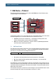
7 CAN Demo – Protocol
This chapter describes the proprietary protocol (below called EACAN) used in the CAN demo when
sending messages over the CAN network.
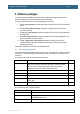
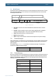
Figure 35 – Example of EACAN network
A CAN network consists of two or more CAN nodes, but on the EACAN network one of these nodes
have been assigned the role of Controller while the rest are considered to be Nodes.
Controller (LPC1769 side on AOAA board) – is responsible for detecting Nodes on the
network, start subscriptions, read and modify node capabilities.
Node (LPC11C24 side of AOAA board) – provides a number of capabilities/peripherals that
can be read and/or modified by the Controller.
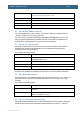
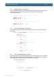
7.1 CAN Frame Format
The CAN Frame format consists of many fields, some of which the application layer will never need to
know about (such as Start-of-frame, CRC, …). Below is a simplified view of the frame format with the
parts that are of most interest when describing the EACAN format.
Figure 36 – Simplified view of CAN Frame Format
ID: Identifier for the data (the Base frame format is used with an 11-bit identifier)
DLC: Data Length Code which specifies number of data bytes (0 – 8) in the Data field
Data: Data to be transmitted
The identifier (ID) is used to uniquely identify a CAN node on the CAN bus. This is necessary since all
nodes on the CAN bus can see all messages. If two nodes would send out messages at the same time
a prioritization between the messages is done based on the identifier. The lower the identifier value the
higher priority on the CAN bus.
The fact that all CAN nodes on a network can see all messages is used in the EACAN format to create
broadcast messages (also called common messages), see section 7.2.1 below.
CAN network
Node
Node
Node
Node
Controller
ID
DLC
Data