
User manual


AOAA Kit - User’s Guide
Page 11
Copyright 2012 © Embedded Artists AB
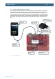
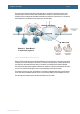
3.3 Step 2: Connect and Power the Board
The picture below illustrates the basic setup of the AOAA board. The Android device is connected to
the USB Host interface of the AOAA board, using the normal USB charger cable (that came with the
Android device). The Android device’s charger is used to power the AOAA board. It actually also
powers the Android device via the USB Host interface. The USB cable between the USB charger and
the AOAA board is included in this kit. It is also possible to power the board via an external +5VDC, 1A
power supply. Note that only one external source should power the AOA board at any given point in
time.
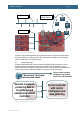
Figure 1 – The AOAA Board Setup
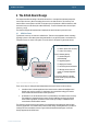
The Android device
(not included)
Android device
charger (not included)
USB-A to
USB-micro B cable
(not included)
USB-A to USB-B
cable (included)
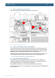
CAN node with
LPC11C24
Prototype area
(100 mil pitch grid of holes)
Alternative external
+5V supply (via
standard 2.1 mm jack)
Android Open
Accessory with
NXP’s LPC1769