
User manual


AOAA Kit - User’s Guide
Page 12
Copyright 2012 © Embedded Artists AB
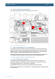
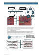
3.4 Step 3: Verify Default Jumper Settings
Verify that the default jumper positions on the board are correct, as below.
Figure 2 – The AOAA Board Default Jumper Positions
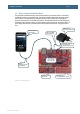
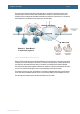
3.5 Step 4: Install USB Driver for Console Output/ISP
The AOAA Board contains an USB-to-UART bridge chip (FT232R from FTDI) that connects UART
channel #0 on the LPC1769 to a virtual COM port on the PC/laptop (via USB). This UART channel is
typically used as the console channel for applications. Printf() output can for example be directed to
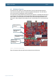
this UART channel. To locate the (mini-B) USB connector, J16, see Figure 20.
A USB driver must be installed on the PC/laptop in order for the virtual COM port to be created. See
FTDI’s installation guides for details how to install the driver for different operating systems:
http://www.ftdichip.com/Support/Documents/InstallGuides.htm
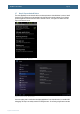
3.6 Step 5: Download Demo Application
Download the selected demo application into the LPC1769. See section 5.1 for details how to
download an application. For simplicity and quickest way forward, it is recommended to start with
downloading via Flash Magic (i.e., using the UART-to-USB bridge).
Precompiled binary images (i.e., bin-files) can be downloaded from the support page.
There is no need to update the LPC11C24 application. It is pre-programmed with a suitable application
from production test.