
User manual


AOAA Kit - User’s Guide
Page 20
Copyright 2012 © Embedded Artists AB
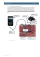
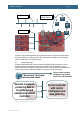
Figure 12 – CAN Node Detached from AOAA Board
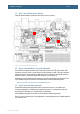
There is a possibility to extend the CAN network via either a DSUB9 (J6) or RJ45 (J5) connector.
These connectors are not mounted but can easily be soldered, if needed. The connectors follow
standard CAN pinning, see tables below.
The CAN interface connectors on the LPC11C24 node are overlapping. Only one type of connector at
a time can be used.
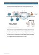
The CAN network can be extended via normal Ethernet (cat 5 or cat 6) or DSUB-9 cabling.
9 pin Male DSUB
8 pin RJ45
Pin
Signal Name
Signal Description
Pin
Signal Name
Signal Description
1
Reserved
Upgrade path
1
CAN_H
Dominant high
2
CAN_L
Dominant low
2
CAN_L
Dominant low
3
CAN_GND
Ground
3
CAN_GND
Ground
4
Reserved
Upgrade path
4
Reserved
Upgrade path
5
CAN_SHLD
Shield, optional
5
Reserved
Upgrade path
6
GND
Ground, optional
6
CAN_SHLD
Shield, optional
7
CAN_H
Dominant high
7
CAN_GND
Ground
8
Reserved
Upgrade path
8
CAN_V+
Power, optional
9
CAN_V+
Power, optional
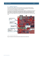
Figure 13 illustrates how the CAN node can be removed from the AOAA board. An Ethernet cable and
RJ45 connectors are used to create the CAN network.