
User manual

AOAA Kit - User’s Guide
Page 22
Copyright 2012 © Embedded Artists AB
4.3 RF Network Expansion
There are two interfaces on the AOAA board for radio modules. One at a time can be used.
Both types of radio modules exist in different (application) versions. This gives the flexibility to create
different types of radio node networks, for example pure ZigBee network, proprietary network based on
IEEE 802.15.4, WiFi (IEEE802.11abgn) and 6LowPAN with different underlying radio standards. The
network topology can be point-to-multipoint or mesh, depending on how the used radio modules are
programmed. The flexibilities are endless!
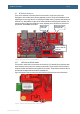
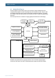
Figure 15 – Radio Module Interfaces on the AOAA Board
4.3.1 NXP’s/Jennic JN5148 module
The interface to this module is on the bottom side of the board. Two alternatives are supported; either
direct soldering to pads on the pcb or mounting on pin headers. The pin headers must be soldered to
the board manually. Note that these pin headers are not included. The pin headers match the JN5148
modules that are shipped with Jennic’s/NXP’s evaluation kits.
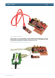
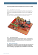
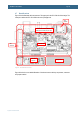
Figure 16 illustrates a radio module that has been soldered to the bottom side of the AOAA board.
Figure 16 – NXP/Jennic Radio Module Mounting on Bottom Side
General expansion
connector with SPI,
UART, etc.
NXP/Jennic pads
on bottom side
XBee socket
on top side