
User manual

AOAA Kit - User’s Guide
Page 23
Copyright 2012 © Embedded Artists AB
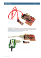
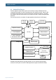
There is support for application download into the JN5148 module via a FTDI UART-to-USB cable that
is connected to pin header J8.
4.3.2 Digi’s XBee family of radio modules
The interface to this module is located on the top/component side of the board. The form factor is
simple to use and program and there are many different versions of the module. Note that there are
also several radio modules on the market that build upon the same form factor as the Digi’s XBee
module.
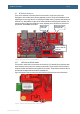
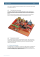
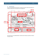
Figure 17 illustrates how the XBee module is mounted in the socket on the top side of the AOAA
board. One of the demo applications for the AOAA board uses XBee Series 1 modules.
Figure 17 – Radio Module Interfaces on the AOAA Board
4.3.3 Serial Expansion Connector
It is also possible to add radio modules via the Serial Expansion Connector. This universal interface
connector contains SPI/UART/I
2
C/GPIO interfaces. Some radio modules on the market prefer to use
the SPI interface instead of UART communication (which is used for the two main radio module
interfaces on the AOAA board).
4.4 Ethernet network expansion
The Ethernet interface is very straightforward. It supports 100/10 Mbps operation, auto-negotiation and
HP Auto-MDIX. There is an lwIP port for the board that is a good starting point for creating TCP/IP
networks on top the Ethernet network. Besides creating local Ethernet networks the AOAA board can
be connected to Internet gateways for global Internet access.