
User manual

AOAA Kit - User’s Guide
Page 26
Copyright 2012 © Embedded Artists AB
4.7 Board Overview
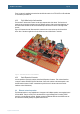
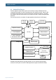
Figure 19 below illustrates the board structure. The upper part is the LPC1769 side of the design. The
lower part contains the LPC11C24 CAN node and a prototype area.
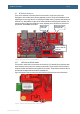
Figure 19 – The AOAA Board Overview
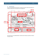
Figure 20 below is a more detailed illustration of the board structure with key components, connectors
and jumpers marked.
CAN
connectors
LPC11C24
CAN node
LPC1769 side
Prototype area
Communication interfaces (Ethernet,
USB H/D, RF modules) and power input
uSD
interface