
User manual

AOAA Kit - User’s Guide
Page 28
Copyright 2012 © Embedded Artists AB
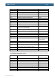
Pin 11 (P0_9)
P0_10
Connected to protected IO, pin 5 of J13
Pin 13
P0_11
connected to protected IO, pin 6 of J13
Pin 15
P0_15, P0_16
UART#1 connected to RF modules
P0_17
Optionally connected to XBee module as CTS signal
Pin 17
P0_18
Power control of uSD interface and connected to
protected IO, pin 7 of J13
Pin 19
P0_19
Card detect input from uSD interface
Pin 21
P0_20
Optionally connected to XBee module as DTR signal
Pin 23
P0_21
Not used, free for expansion
Pin 25
P0_22
Optionally connected to XBee module as RTS signal
Pin 27
P0_23
Analog inputs #0 connected to serial expansion
connector and protected IO, pin 1 of J13
Pin 29
P0_24
Analog inputs #1 connected to protected IO, pin 2 of
J13
Pin 31
P0_25
Analog inputs #2 connected to protected IO, pin 3 of
J13
Pin 33
P0_26
Analog inputs #3 or analog output connected to serial
expansion connector and connected to protected IO,
pin 4 of J13
Pin 35
P0_27, P0_28
I2C interface connected to serial expansion connector
and E2PROM
Pin 37 (P0_27),
Pin 39 (P0_28)
P0_29, P0_30
USB interface, either Host or Device
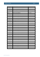
P1_0 – P1_17
Ethernet interface
P1_18
USB UP LED control
P1_19
USB Host power control
P1_20
Not used, free for expansion
Pin 41
P1_21
Not used, free for expansion
Pin 2
P1_22
USB Host VBUS monitor input
P1_23
Connected to open drain output OUT1 of J11
Pin 4
P1_24
Connected to open drain output OUT2 of J11
Pin 6
P1_25
Connected to open drain output OUT3 of J11
Pin 8
P1_26
Connected to open drain output OUT4 of J11
Pin 10
P1_27
USB Host distribution switch over-current status input
P1_28
Not used, free for expansion
Pin 12
P1_29
Not used, free for expansion
Pin 14
P1_30
USB Device VBUS input
P1_31
Analog input #5 connected to trimming pot. R93