
User manual

AOAA Kit - User’s Guide
Page 29
Copyright 2012 © Embedded Artists AB
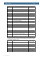
P2_0
Connected to red LED in RGB-LED D6
Pin 16
P2_1
Connected to blue LED in RGB-LED D6
Pin 18
P2_2
Connected to green LED in RGB-LED D6
Pin 20
P2_3
Connected to red LED in RGB-LED D7
Pin 22
P2_4
Connected to blue LED in RGB-LED D7
Pin 24
P2_5
Connected to green LED in RGB-LED D7
Pin 26
P2_6
Not used, free for expansion
Pin 28
P2_7
Not used, free for expansion
Pin 30
P2_8
Not used, free for expansion
Pin 32
P2_9
USB Device connection control
P2_10
Boot load enable input controlled from automatic ISP
function of UART-to-USB bridge
Pin 34
P2_11
Connected to push button SW2 (KEY1)
P2_12
Connected to push button SW3 (KEY2)
P2_13
Connected to protected IO, pin 8 of J13
Pin 36
P3_25
Connected to serial expansion connector
Pin 38
P3_26
Connected to serial expansion connector
Pin 40
P4_28 – P4_29
UART#3 connected to serial expansion connector
Pin 42 (P4_28),
Pin 44 (P4_29)
Ground
Power supply
Pin 46, 48, 50
RESET_IN
Reset input to LPC1769
Pin 43
VREF
Reference voltage to ADC of LPC1769 (is an output, no
external voltage should be supplied to this pin)
Pin 45
+3.3V
Power supply
Pin 47
+5V
Power supply
Pin 49
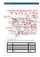
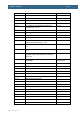
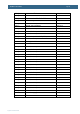
The table below lists how the LPC11C24 pins are used in the design and where the pins are available
on the expansion connector pair, J19/J20.
LPC11C24 pin
Usage
Expansion
connectors (J19/20)
PIO0_0
Reset
J19, pin 1
PIO0_1
Not used, free for expansion
J19, pin 2
PIO0_2
Not used, free for expansion
J19, pin 3
PIO0_3
Connected to interrupt output of light sensor
J19, pin 4
PIO0_4
I2C-SCL connected to temperature and light sensors
J19, pin 5
PIO0_5
I2C-SDA connected to temperature and light sensors
J19, pin 6
PIO0_6
Not used, free for expansion
J19, pin 7