
User manual

AOAA Kit - User’s Guide
Page 31
Copyright 2012 © Embedded Artists AB
4.9 Schematic Walkthrough
4.9.1 Page 2
The center of the AOAA board is the LPC1769 from NXP. It is a MCU based on the ARM Cortex-M3
core. LPC1769 has many communication interfaces, which are used on the AOAA board.
The external crystal is 12MHz, which is the recommended value to get standard CAN timing and
meeting the USB frequency requirements. The RTC crystal is not mounted since AOAA board is not a
low-power design. It will always be powered. The RTC can derive its clock from the main oscillator.
J1 is the SWD interface for LPC1769, i.e., debug interface. It is the new and smaller footprint standard
ARM debug connector. It has 2x5 pins in 50 mil pitch.
4.9.2 Page 3
The LPC1769 has one USB port that can act as either device or host. The AOAA board contains one
USB Device interface and one USB Host interface. At any given point in time, one of them can be
used. JP1/JP2 selects which USB interface the LPC1769 USB port is connected to.
The USB Device interface is very straight forward and consists of a USB-B connector (J2), ESD
protection, VBUS sense and DP pull-up resistor control.
The USB Host interface is also very straight forward and consists of a USB-A connector (J3), ESD
protection, VBUS distribution switch (U2) and VBUS/distribution switch status sense.
4.9.3 Page 4
The LPC1769 Ethernet interface is connected to an external Ethernet PHY (U3), LAN8720 from
SMSC, via the standard RMII interface. The LAN8720 chip generates the needed 50MHz clock from
an external 25MHz crystal. The RJ45 connector (J4) contains integrated magnetic.
There is a 32kbit I
2
C E
2
PROM (U5) for storing non-volatile parameters, like MAC address. The I2C
address to the 24LC32AT chip is 0xA0 (1.0.1.0.0.0.0.rw). Details about the 24LC32AT chip operation
can be found in the datasheet.
4.9.4 Page 5
The LPC1769 CAN interface is connected to an external CAN transceiver (U6). The on-board CAN
network connects directly to the LPC11C24 CAN node. There is a possibility to extend the CAN
network via either a DSUB9 (J6) or RJ45 (J5) connector. These connectors are not mounted but can
easily be soldered, if needed. The connectors follow standard CAN pinning.
The Serial Expansion Connector (J7) is a 14-pin standardized connector on Embedded Artists boards.
The connector carries UART/I
2
C/SPI/GPIO signals, allowing for flexible expansion to external devices.
4.9.5 Page 6
UART#1 of the LPC1769 can be connected to a radio module. Two interfaces are supported:
NXP’s/Jennic JN5148 module
The interface to this module is on the bottom side of the board. Two alternatives are
supported; either direct soldering to pads on the pcb or mounting on pin headers. The pin
headers must be soldered to the board manually. Note that these pin headers are not
included. The pin headers match the JN5148 modules that are shipped with Jennic’s/NXP’s
evaluation kits.
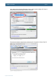
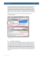
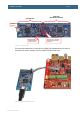
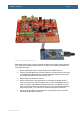
o There is support for application download into the JN5148 module. Connect a FTDI
UART-to-USB cable (FTDI part no. TTL-232R-3V3, Digikey part no. 768-1015-ND) to
J8 and keep SW1 pressed while pressing and releasing the reset push button, SW4.
The JN5148 modules in now in a bootload mode accepting application download via
Jennic’s/NXP’s flash download application.