
User manual


AOAA Kit - User’s Guide
Page 45
Copyright 2012 © Embedded Artists AB
6 Troubleshooting
This chapter contains information about how to troubleshoot boards that does not seem to operate
properly. It is strongly advised to read through the list of tests and actions that can be done before
contacting Embedded Artists support. The different tests can help determine if there is a problem with
the board, or not. For return policy, please read Embedded Artists’ General Terms & Conditions
document. This document can be found on the Embedded Artists’ web site.
6.1.1 Cannot download/debug
Symptom: Cannot contact the LPC1769 or LPC11C24 via SWD
Check powering, check that the SWD interface works on another board.
Cause: An erroneous application program can disable the SWD interface and/or program the internal
clocks in the wrong way so that it is impossible to download a new application to the board. The
erroneous application program starts executing after a reset and initializes the LPC1xxx in the wrong
way before an external debugger can get control over the processor.
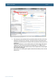
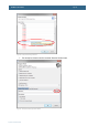
Solution: Use FlashMagic on the LPC1769 to erase the flash completely. On the LPC11C24, pull
PIO0_1 low while power cycling the board (= resetting the LPC11C24). This way the ‘known good’
internal bootloader starts executing. From this state, it is possible for an external debugger to get
control over the processor and download a new application program.
6.1.2 Verify operation of board
Symptom: The AOAA board does not seem to operate properly.
Solution: Perform a complete verification of the board.
The first step is to make sure that powering works properly. Make sure that all jumpers are in their
default position, see section 3.4 for details.
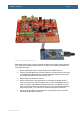
Connect a USB charger to J14 (or an external +5VDC, 1A supply to J15). Test points TP2, TP3 and
TP4 are located just above the LPC1769. Measure the voltage between TP3 and TP4. The voltage
shall be between 4.5 and 5.5V. Measure the voltage between TP2 and TP4. The voltage shall be
between 3.15 and 3.34V.
The second step is to download the production test application into the board. Since there are two
processors on the AOAA board, both needs to be programmed. Normally the LPC11C24 (CAN node)
is not changed so the default application is most likely still programmed on this processor. See section
5.1 for details how to download an application.
1. The following material is needed to perform a full test of the board:
USB cable (mini-B to A) for console output
Ethernet cable
USB keyboard
Micro SD card with the file testfile.txt (see zip-file from support page when downloading
the test application).
2. Prepare the AOAA board for test:
Connect the USB cable (B to A) to an USB charger or external power supply
Connect the USB cable (mini-B to A) to a PC
Connect the Ethernet cable to a PC (preferably local connection – the PC shall not be
connected to a network)
Connect a USB keyboard to the USB Host connector of the AOAA board.