
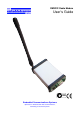
User`s guide


Installation 2-1
Chapter 2
Installation and Operation
This chapter describes basic connection procedures and operation. It also covers the
front panel indicator lights and physical mounting and positioning of the radio modem.
Serial Interface
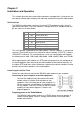
The RMX232 radio modem interfaces to external DTE equipment using a 9 way D
type female connector. The serial interface is configured as DCE equipment with the
pin out shown in the table below.
Pin Name DCE Function
2 RXD Receive Data (out)
3 TXD Transmit Data (in)
4 DTR Data Terminal Ready (in)
5 SG Signal Ground
7 RTS Ready To Send (in)
8 CTS Clear To Send (out)
The serial protocol supported by the radio modem is fixed at 8 data bit, 1 stop bit and
no parity. Flow control can be user selected as either hardware (RTS/CTS), software
(XON/XOFF) and none. The serial baud rate is also user configurable and supports
the following rates: 600, 1200, 2400, 4800, 9600, 14400, 38400, 57600, and 115200.
When operating the radio modem at a DTE baud rate greater than the configured on-
air data throughput, data received by the radio modem will be buffered internally. At
the higher DTE baud rates either hardware or software flow control should be used to
prevent receive buffer overflows in the radio modem.
Connecting for the First Time
Follow the steps below to connect the RMX232 radio modem to your computer.
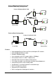
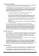
Connecting to your computer or terminal equipment
Connect the supplied 9 way data cable to the radio
modem and to a suitable serial data port on your
computer. If the serial data port on your computer is a
25 way connector, you will require a suitable 9 way to
25 way adapter. The D9 DTE (host) to D9 DCE (radio
modem) pin connection diagram is shown in the
diagram opposite.
Supplying power to the Radio Modems
The RMX232 radio modem requires a 9-15VDC power source to operate. A
reliable external power source is strongly advised when running the radio
modem continuously.
User’s Guide