Quick Manual - FDM Field Data Monitoring 1
Abbreviations B2B BMC BMS CAN CAT CV DC DoD EMC EMI FCC FDM GSM HV HVIL LTE QM PE RF SoC SoH VIB VIC Business to Business Battery Management Controller Battery Management System Controller Area Network Categorie Commercial Vehicle Direct Current Depth of Discharge Electromagnetic Compatibility Electromagnetic Interference Federal Communications Commission Field Data Monitoring Global System for Mobile Communications High Voltage High Voltage Interlock Long Term Evolution Quality Management Potential Equali
Contents 1 Introduction ................................................................................................................................................. 4 2 General Information about FDM ................................................................................................................. 5 2.1 Supported Countries ......................................................................................................................... 5 2.2 System Diagram....................
1 Introduction The FDM Quick Manual gives an overview of the characteristics and functions of the Field Data Monitoring device (FDM) which is used alongside the battery pack and battery management system (BMS) developed by Webasto for use in commercial vehicles (CV). Important installations rules can also be found in this document.
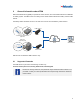
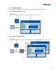
2 General Information about FDM With Field Data Monitoring (FDM) it is possible to collect, transmit, save and visualize data from the Webasto CV battery system. The FDM control unit is acting as the central interface between the battery and the mobile network. The battery data is transferred via 2G or LTE CAT M1 to a server and visualized by a web frontend. FDM Connect Single Pack Application Multi Pack Application (VIB) Server Web frontend FDM Connect FDM Connect is intended for B2B commerce only.
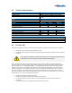
2.2 System Diagram The power supply of the FDM as well as the battery system shall be provided from the vehicle. 2.2.1 Single pack battery system 2.2.
2.3 Technical Characteristics Features Network module GNSS module CAN Body Weight Material Power Voltage (Vbb, V+)* Power consumption (Ibb average at 24 VDC) * Terminal 30 connection Environment Moisture Operating temperature IP classification* Quad-band GSM, LTE CAT M1 BeiDou, Galileo, GLONASS, GPS / QZSS 2.
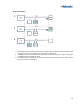
3 Mechanical Information The dimensions of the FDM are 112.2 mm x 69.6 mm x 18.72 mm. Two mounting holes of each 4.5mm can be used to fix the FDM.
4 Electrical Interfaces 4.1 Connector The FDM has a 10 pol Molex connector. The counterpart connector is Molex 43025-1200 with socket contacts Molex 43030-0002. Matching derivats can be used as well. 4.
Single Pack Battery: 1. 2. 3. The FDM device is connected somewhere on the vehicle CAN via a stub line, but is not the first or last CAN device on the bus. The FDM device must not have a termination. The FDM device is the last device to be connected to the vehicle CAN via the CAN line of the VIB. The FDM must be terminated with 120 Ω. The FDM device is connected on the vehicle CAN between VCU and VIB via a stub line. The FDM device must not have a termination.
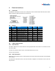
Multi Pack Battery System: 1. 2. 3. The FDM device is connected somewhere on the vehicle CAN via a stub line, but is not the first or last CAN device on the bus. The FDM device must not have a termination. The FDM device is the last device to be connected to the vehicle CAN via the CAN line of the VIB. The FDM must be terminated with 120 Ω. The FDM device is connected on the vehicle CAN between VCU and VIB via a stub line. The FDM device must not have a termination.
5 Vehicle Integration To ensure that the FDM operates properly, it is necessary to observe the following vehicle integration guideline. 5.1 Power Supply The FDM device must be connected to the vehicle terminal 30 and terminal 31 to ensure a consistent data connectivity. 5.2 General Mounting Position The FDM device must be installed inside the vehicle in a dry place. Installation shall be as high as possible to get the best mobile connectivity. The mouting holes can be used to fix the device. 5.
5.3.1 Metal Free Area Metals near the FDM antenna can ruin RF performance. To avoid this, the unit must be mounted so that there is no metal 3 cm around the unit. 5.3.2 Routing of Cables Any cables or wiring harnesses - including the own FDM wiring harness - should also not be routed near the FDM antenna. 5.3.3 Avoid other Control Devices Also, other devices i.e. vehicle control modules, airbags, radios and other antennas should not be near the FDM device because transmitted RF signals can cause problems.
5.