
Full Product Manual


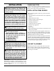


ON
POSITION
OFF
POSITION
GRH/OV 020MANUAL SHUT-OFF VALVE
10
Figure 14 - Equipment Shutoff
Valve
Open
Closed
Equipment
Shutoff
Valve
PRESSURE TESTING APPLIANCE
GAS CONNECTIONS
1. Open equipment shutoff valve (see Figure 14).
2. For natural gas, open main gas valve located on or near
gas meter. For propane/LP gas, open propane/LP supply
tank valve.
3. Make sure control knob of fireplace is in the OFF posi-
tion.
4. Check all joints from equipment shutoff valve to gas
control valve. Apply noncorrosive leak detection fluid
to all joints. Bubbles forming show a leak.
5. Correct all leaks at once.
6. Light fireplace (see Operating Log Set, page 13). Check
all other internal joints for leaks.
7. Turn off fireplace (see To Turn Off Gas To Log Set, page
14).
INSTALLATION
Continued
Test Pressures Equal To or Less Than 1/2
PSIG (3.5 kPa)
1. Close equipment shutoff valve (see Figure 14).
2. Pressurize supply piping system by either opening
propane/LP supply tank valve for propane/LP gas or
opening main gas valve located on or near gas meter of
natural gas or using compressed air.
3. Check all joints from gas meter to equipment shutoff
valve for natural gas or propan
e/LP supply to equipment
shutoff valve for propane/LP. Apply noncorrosive leak
detection fluid to all joints. Bubbles forming show a
leak.
4. Correct all leaks at once.
BATTERY
INSATLLATION
Batteries must be installed in the appliance for it to funct-
ion. There are four “C”-cells in the burner system, and
two “AAA” cells in the handset.
1. Remove the two phillips screws at esch side of the bat-
tery holder and remove holder. Be carefull with the at-
tached wires. (see figure 15)
2. install batteries into the holder, minding the polarity of
each cell.
3. carefully reinstall the battery holder into the burner sy-
stem, again minding the wires.
4. Replace the two screws.
Figure 15 - Burner System switches and Battery
location
LEARN
HI/LOW ON/OFF
I
I
Screws
HANDSET
1. On the back of the handset, slide the battery cover down
and off.
2. Install two “AAA” cells (mind the polarity).
3. replace cover.
BURNER SYSTEM
USING THE “LEARN” FUNCTION
To program your burner system to accept commands from
your handset, the “LEARN” function (see figure 15) is used.
“LEARN” Function
• The LEARN window will remain open for 60-seconds.
• The control will learn up to 3 different transmitter security
codes.
1. Press and release the learn switch to open the LEARN window,
the module will beep indicating the module is ready to accept a
transmitter security code.
2. Press a transmitter button to send any command, the module
will generate a series of beeps indicating a signal was received.