
Instructions / Assembly


4
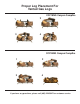
D. Prefabricated replace. Refer to the manufactures replace instruction manual for speci c information regarding
the running of a gas line into that particular model. A typical prefab installation involves the insertion of a 1/2 inch
gas pipe through the gas line tube provided by each manufacturer from outside the replace. The Knockout on the
inside of the replace is removed as the gas pipe is punched through the replace. (See Figure 3.)
E. Masonry replace. A 1/2 inch gas supply line must be provided to the rebox. Most installations require drilling an
access hole through the masonry wall. The supply line should be secured and sealed by mortar within the access
hole. The supply line should also have an on-off valve either in the wall or inside the replace. (See Figure 4.)
GAS LOG INSTALLATION
(See Figure 1 Parts List as a guide to reference part numbers.)
BURNER PAN INSTALLATION
NOTE: Use pipe compound on all male threads to seal joints.
A. Determine if the replace has a right or left-hand gas line feed.
The circular “Dimpled” hole covering must be knocked out on the
appropriate (right or left) side of the burner pan. NOTE: Brace pan
on workbench when removing burner knockout. Strike knockout with
nailpunch for easy removal.
B. Locate 3/8” locknut (Part #12) and washer (Part #21), then fasten
them to the 3/8” brass ori ce elbow (Part #11). Do not fasten the
locknut on the “ ared” end.
C. Slide the 3/4” burner support spacer (Part # 10) over the Dual Burner
Bar (Part #9) and move spacer to opposite corner of the gas intake
connection. (See Figure 5)
D. Secure the intake end of the Dual burner bar (Part # 9) to the burner
pan (Part # 8) through the knockout hole selected (right or left hand)
with the 3/8” brass ori ce elbow (Part # 11) , 3/8” locknut (Part # 12)
and washer (Part #21) previously assembled in Step B.(See Figure 6.)
E. Tighten elbow until rmly attached to the Dual burner bar. Then, rmly
tighten the attached lock-nut on the elbow to seal the burner bar to the
wall of the burner pan.
Figure 3. Gas line installation - Prefabricated Fireplace
Figure 4. Gas line installation - Masonry Fireplace
Figure 5. Burner bar placement
Figure 6. Burner bar connection