
Instructions / Assembly


5
CONNECTING GAS SUPPLY TO BURNER ASSEMBLY
(If a Safety Pilot Kit is to be used, please refer to separate installation instructions.) These instructions refer to
Natural Gas applications installed without a Safety Pilot Kit. LP/NG Safety Pilot Kit available at your local store.
A. Place burner pan assembly in the center of the replace.
B. Attach 3/8” Flare X 1/2” NPT gas valve (Part #13) to the 1/2 inch gas supply stub already in fireplace.
Be certain connections are tight and use pipe compound on all male NPT (pipe) threads to seal joints
C. Attach 3/8” flared tubing (Part #15) to burner pan assembly. Attach opposite end to gas supply line by carefully
bending the ared tubing as needed to make the connection. Avoid kinking the flared tubing while bending. If tubing
must be cut, use a tube cutter. Flare the cut end of the tube with a
a
r
i
n
g
t
o
o
l
.
NOTE: A good method of bending the tube is to ll it with sand, bending the tube as needed to make the
connection. This method will eliminate kinking in the line. Once the tube is in the desired con guration for hookup,
be sure to empty the tube completely of any sand before tube is connected to the gas supply line and the burner.
D. Be certain all connections are tight. Only use pipe compound on all male NPT (pipe) threads. Test all connections
with a soapy water solution with the gas supply turned on. If bubbles appear on any connection, retighten and retest.
Once it is determined there are no leaks whatsoever, turn off gas supply and move to next assembly step.
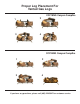
GRANULE, EMBER AND GRATE PLACEMENT
A. Spread granules (Part # 16) over the installed burner pan. Granules
should be sloped to the same angle as the burner pan lling the entire
pan. (See Figure 7A.)
B. Spread glowing embers (Part # 17) evenly over the top of the granules
covering the entire surface area, concentrating on the front and sides of
the burner pan for the most realistic burning effect.
C. Place log grate (Part # 7) over the burner pan aligning as shown.
(See Figure 7B.)
D. Attach back log Standoff (Part # 18) to the back part of the grate.
(See Figure 7B.)
NOTE: A hammer may be used to tap the back log standoff in place.
It may be necessary to squeeze the back log standoff with pliers after
attaching to the grate.
LIGHTING YOUR GAS LOG SET
(Manual Valve only)
A. Open chimney ue damper to the full open position.
B. Be sure gas supply is shut off.
C. Lay match on top of embers and granules near gas burner input.
Do not hold match in hand. (See Figure 8.)
D. With match burning, slowly turn on gas.
Figure 7 (A & B) Granule and
Grate Placement
Figure 8. Lighting the log set