
Installation Guide


Valve Body Assembly (cont.)
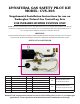
7. Attach pilot gas supply line (Part # 6) to the bottom of the gas control
valve. Care should be taken not to kink the tubing which would restrict
gas ow to the Pilot Burner. (See Figure 23)
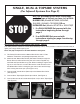
8. Carefully bend the supply line in a smooth 90 degree angle to prevent the
line from being kinked. (See Figure 24)
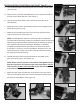
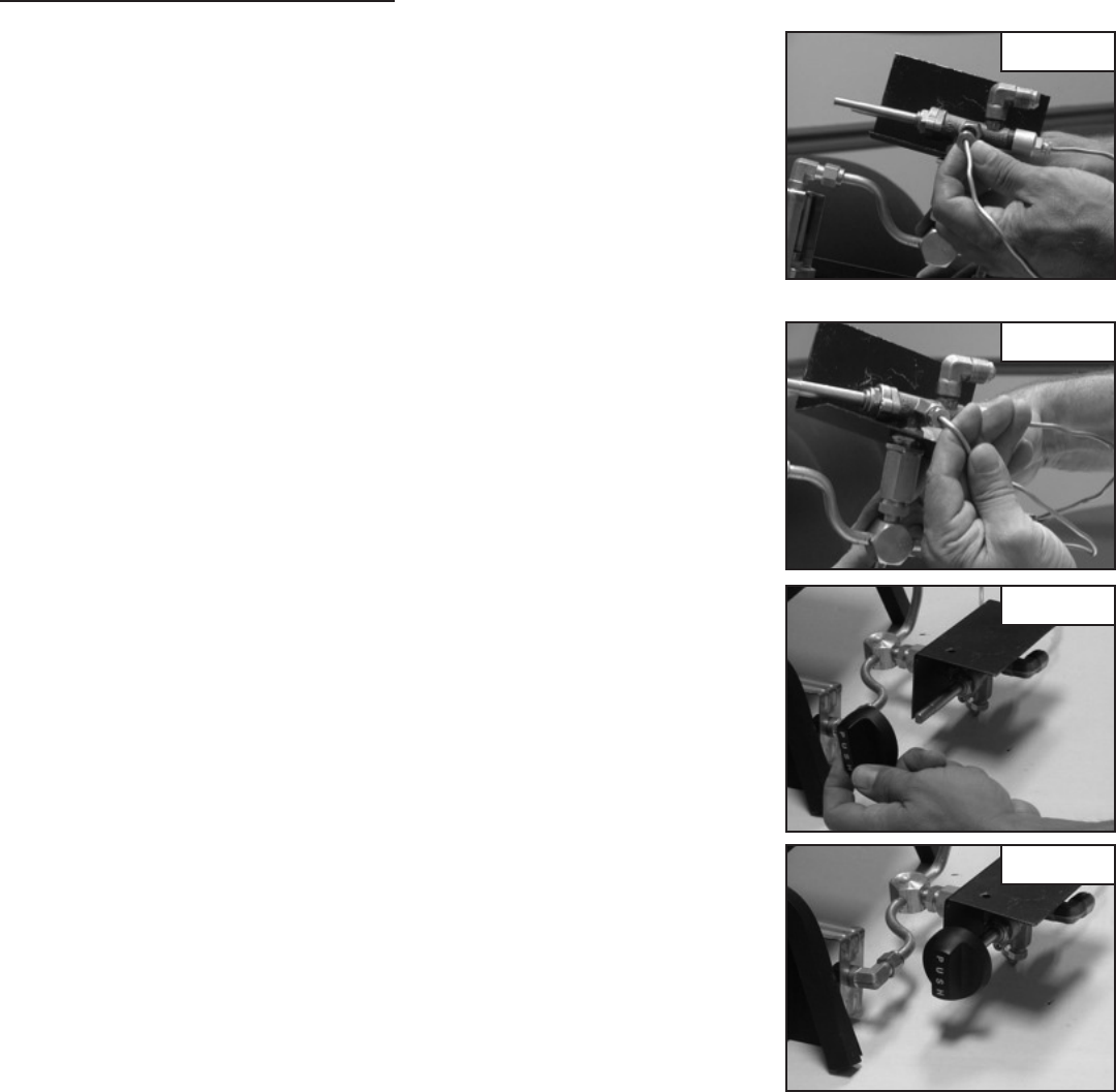
9. Connect control knob (Part # 1) to gas control valve stem.
(See Figures 25 & 26)
NOTE: Tighten all ttings securely with a wrench.
10. Place the assembled burner pan with gas control valve in the center of
the replace.
11. Connect the 1/2” gas supply line from the replace to the 3/8” straight
ared tting (Part # 4) with the 3/8” ared tubing supplied with gas
log set. Refer to General Installation Instructions section titled,
“Connecting Gas Supply to Burner Pan” for full instructions.
12. Test connections for leaks with soapy water, re-tighten if necessary and
re-test to determine if any leaks are present.
13. Refer to General Installation Instructions for Granule, Ember, Grate and
Log Placement.
Figure 24
Figure 25
Figure 23
Figure 26