
Installation Guide

ON
POSITION
OFF
POSITION
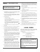
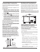
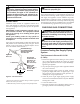
GRH/OV 020MANUAL SHUT-OFF VALVE
Figure 6 - Equipment Shutoff Valve
Open
Closed
Equipment
Shutoff
Valve
PRESSURE TESTING APPLIANCE
GAS CONNECTIONS
1. Open equipment shutoff valve (see Figure 14).
2. For natural gas, open main gas valve located on or near
gas meter. For propane gas, open propane gas supply
tank valve.
3. Make sure control knob of fireplace is in the OFF posi-
tion.
4. Check all joints from equipment shutoff valve to gas
control valve. Apply noncorrosive leak detection fluid
to all joints. Bubbles forming show a leak.
5. Correct all leaks at once.
6. Light fireplace (see Operating Log Set, page 13). Check
all other internal joints for leaks.
7. Turn off fireplace (see To Turn Off Gas To Log Set, page
14).
INSTALLATION
Test Pressures Equal To or Less Than 1/2
PSIG (3.5 kPa)
1. Close equipment shutoff valve (see Figure 6).
2. Pressurize supply piping system by either opening
propane gas supply tank valve for propane gas or op-
ening main gas valve located on or near gas meter of
natural gas, or by using compressed air.
3. Check all joints from gas meter to equipment shutoff
valve for natural gas or propane supply to equipment
shutoff valve for propane gas.
Apply noncorrosive leak
detection fluid to all joints. Bubbles forming show a
leak.
4. Correct all leaks at once.
CONTINUED
10
WALL MOUNTED SWITCH
(INSTALLER SUPPLIED)
INSTALLATION SHOULD BE DONE BY A
QUALIFIED INSTALLER FAMILIAR WITH
LOW-VOLTAGE WIRING PROCEDURES.
WARNING: Do not connect this
switch or log set to any electrical
source! Electrical shock and/or
fire hazard will occur.
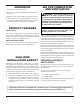
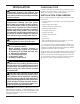
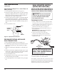
Connecting to Log Set
1. Remove “Jumper wire” from back of terminal block
on control valve. Connect one terminal of the wire to
“TH/TP” terminal on the control valve (see Figure 7).
2.
Connect remaining wire terminal to the “TH”
terminal on the control valve (see Figure 7).
3.
Route the 18ga.wire (maximum length of 25ft.) to a
convenient location.
IMPORTANT: The 18ga. wire may be shorter
Than 25”,
but must not be longer.
4. Connect one bare wire end to each of the
terminals of the installer provided wall switch.
5.
Install the wall switch and cover onto the switch
installed in the wall.
AUTO
OFF
ON
Thermopile
Wall Mounted
Switch
Figure 7
NOTICE: You must light the pilot
before using the Wall Mounted
-
Switch - See Lighting Instruct-
tions in your manual.
After lighting, let pilot flame burn for about one minute.
You can now turn the burner on and off with the Wall
Switch.
Turn control knob to ON position. Adjust flame
adjustment knob anywhere between HI and LO.
-
Note: The burner may light if Wall Switch was
on when the burner was last turned off.