8DBNL-60 AND 24DBNL-60 Tested & Listed By VENTED DECORATIVE APPLIANCE Convertible from Natural Gas to Propane/LP Gas C US Z21.
Safety ............................................................... 2-3 Product Identification ........................................... 3 Local Codes .........................................................4 Unpacking ............................................................4 Product Features ................................................. 4 Installation ............................ ........................ 4-10 .............. 19 Operation .. ......................................................
SAFETY Continued 5. You must operate this log set with fireplace screens in place and fully closed. Unless provided by other means, fireplace doors or screens shall have openings for introduction of combustion air. 11. Do not run log set: • where combustible materials, gasoline and other flammable vapors and liquids are used or stored • under dusty conditions 6. This log set is designed to be smokeless. If logs ever appear to smoke, turn off appliance and call a qualified service person.
UNPACKING LOCAL CODES Install and use log set with care. Follow all local codes. In the absence of local codes, use the latest edition of The National Fuel Gas Code ANSIZ223.1/NFPA 54*. CAUTION: Do not remove the metal data plates from the burner pan. The data plates contain important warranty and safety information. . *Available from: American National Standards Institute, Inc. 1430 Broadway New York, NY 10018 National Fire Protection Association, Inc. Batterymarch Park Quincy, MA 02269 1.
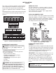
INSTALLATION Continued The charts in Figure 2 indicate technical information regarding the installation of your gas log set. Please make sure that all of the specifications shown are applicable before installation is attempted. The fireplace must include a working flue and venting system with the minimum openings shown in the Figure 2. LOG SIZE 18" 24" 30" MINIMUM FIREBOX SIZE FRONT BACK MINIMUM WIDTH WIDTH* DEPTH HEIGHT FLUE SIZE 8" dia. 28 " 21" 15 1/2" 16.5" 8" dia. 32 " 24" 15 /2" 18" 36 " 8" dia.
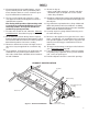
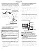
INSTALLATION Continued We recommend that you install a sediment trap in the supply line as shown in Figure 4. Locate sediment trap where it is within reach for cleaning. Install in piping system between fuel supply and heater. Locate sediment trap where trapped matter is not likely to freeze. A sediment trap traps moisture and contaminants. This keeps them from going into log set controls. If sediment trap is not installed or is installed wrong, log set may not run properly.
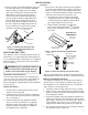
INSTALLATION Continued 4. (Refer to Figure 6 and Illustrated Parts page 22) Assemble the two 3/8” street elbows (part #9) and 3/8“ nipple (part #10) to the 3/8” elbow (#11). Now screw the 3/8” locknut (Part #13) down onto the male threads of the elbow. Place the hole of the Heat Shield (part #12) over the elbow and slide it down against the locknut. Apply pipe compound to the male threads of the elbow and attach it to the control valve. Tighten and adjust the position of the gas control necessary.
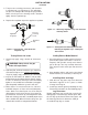
INSTALLATION Continued 5. Turn pressure selecting screw over and reinstall it in regulator cap (see Figure 10-11 ).This will adjust the pressure setting to the LP/Propane gas position. Make sure the pressure selecting screw is installed tightly into the regulator cap. 6. Replace the regulator cap on the appliance regulator.
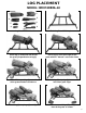
LOG PLACEMENT MODEL: BRO18DBNL-60 2 1 5 3 4 7 8 6 Log Identification Place log (1) onto back left area of the grate, perpendicular to log (2) Back Log Stand-Offs in place Place log (3) at the front right of the grate with the “burned” area to the flame Place “Y” shaped log (4) onto left of the grate ahead of raised area Place log (5) atop log (4), brace on left center grate finger Place log (6) atop logs (1) and (3) Place the two small logs (7) and (8) in front of the grate as shown 9
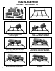
LOG PLACEMENT MODEL: BRO24DBNL-60 8 9 7 3 6 4 1 2 5 Log Identification Place log (1) onto back right area of the grate 10 Back Log Stand-Offs in place Place “Y” shaped log (2) onto left of the grate ahead of raised area Place log (3) onto back left area of the grate, perpendicular to log (1) Place log (4) at the front right of the grate with the “split” area to the flame Place log (5) on to log (2) and brace it on the grate finger left of center Place log (6) atop logs (5) and (4) as shown
LOG PLACEMENT MODEL: BRO24DBNL-60 Cont.
LOG PLACEMENT MODEL MO18DBNL-60/MO24DBNL-60 5 6 4 3 2 1 Back Log Stand-Offs in place Log Identification MO18NG 12 Place Main Front Log (1) onto front area of the grate Place shorter back log (2) onto Back Log Stand-Offs Place Cross-Log (3) at the left side Place Cross-Log (4) at the center Place Cross-Log (5) at the right side Place Cross-Log (6) from the center to the right side
LOG PLACEMENT MODEL MO24DBNL-60Cont. 4 Follow the first five steps from MO18NG on previous page.
LOG PLACEMENT MODEL: SH18DBNL-60 1 2 4 6 5 3 Log Identification 14 Back Log Stand-Offs in place Place main front log (1) onto front area of the grate Place shorter back log (2) onto raised area of the grate Place Cross-Log (3) at the left side Place Cross-Log (4) at the right side Place Cross-Log (5) at the center Place Cross-Log (6) from the center to the right side
LOG PLACEMENT MODEL: SH24DBNL-60 7 5 2 4 1 3 6 Log Identification Place main front log (1) onto front area of the grate Back Log Stand-Offs in place Place shorter back log (2) onto raised area of the grate Place Cross-Log (3) at the left side Place Cross-Log (4) at the center left Place Cross-Log (5) at the center right Place Cross-Log (6) at the right side 15
LOG PLACEMENT MODEL: SH24DBNL-60 cont.
LOG PLACEMENT MODEL CS30DBNL-60 7 9 3 8 2 5 1 4 6 Log Identification Place Right front log (1) onto front area of the grate Place back log (3) onto raised area of the grate Place “Y” shaped Cross-Log (5) at right Back Log Stand-Offs in place Place left front log (2) onto front area of the grate Place Cross-Log (4) at the center left Place Cross-Log (6) from front left to lay on log (5) as shown 17
LOG PLACEMENT MODEL: CS30DBNL-60 Cont.
OPERATION LIGHTING INSTRUCTION FOR YOUR SAFETY READ BEFORE LIGHTING WARNING: Keep flue open when operating unit. WARNING: If you do not follow these instructions exactly, a fire or explosion may result causing property damage, personal injury or loss of life. A. This appliance has a pilot which must be lighted by hand. When lighting the pilot, follow these instructions exactly. B. BEFORE LIGHTING smell all around the appliance area for gas.
CURING THE LOGS LIGHTING INSTRUCTION Continued 9. Slightly push in and turn control- knob counterclockwise to the ON position. 10. To leave pilot lit and shut off burners only: to the PILOT Turn control knob clockwise position, or set selector switch in the OFF position. TO TURN OFF GAS TO APPLIANCE During the 2-3 hour appliance break-in period, you may detect an odor from the appliance as the various paints and compounds used in the manufacturing of this log set cure.
CLEANING AND MAINTENANCE • Keep the area around the log set clean and clear of debris. • Occasionally, you may use a soft bristle brush to clean logs. • Periodically inspect the air mixer and burner tube for foreign matter blocking the air inlet and flame holes. • Once every year a qualified agency or certified chimney sweep should examine and clean the venting system of the fireplace.
TROUBLESHOOTING OBSERVED PROBLEM Delayed ignition burner. Continued POSSIBLE CAUSE 1. Pilot angle needs adjusting. 2.Wrong pilot orifice for gas type. Burner flame is too low or too high. 1. Incorrect ga s supply or pressure. 2. Blocked burner orifice or burner manifold ports. REMEDY 1. Adjust pilot angle for best flame contact with burner pan. 2. Replace pilot orifice. 1. Check for proper gas supply pressure. 2. Free burner orifice and manifold ports of any burrs, paint, or other blockage. 3.
(18,24,30)DBNL - 60 PARTS 22 21 23 2 19 3 18 20 19 7 1 26 6 28 5 4 17 5 L 8 LP Conversion Items 9 16 11 10 15 14 24 13 12 27 25 23
(18,24,30)DBNL - 60 PARTS Continued KEY NO. PART NO. DESCRIPTION 1. SBNCJ00365A Burner Pan 2. SBNCJ00366A SBNCJ00367A RCOCB00002A Burner Pan Burner Pan Burner Tube Burner Tube 3. 4. RCOCB00004A RCOCB00002A RMH-120-00420 RMH-120-90955 18” QTY. 24” QTY. 30” QTY. 1 0 0 1 0 1 0 0 0 0 1 0 1 0 1 0 0 Burner Tube Burner Spacer 1. Gas (18” Set) 1. Orifice, Natural 0 0 1 1 RMH-120-90955 Orifice, Natural Gas (24” and 30” Set) 0 1 1 5.
NOTES ______________________________________________________ ______________________________________________________ ______________________________________________________ ______________________________________________________ ______________________________________________________ ______________________________________________________ ______________________________________________________ ______________________________________________________ ______________________________________________________ __________
NOTES ______________________________________________________ ______________________________________________________ ______________________________________________________ ______________________________________________________ ______________________________________________________ ______________________________________________________ ______________________________________________________ ______________________________________________________ ______________________________________________________ __________
NOTES ______________________________________________________ ______________________________________________________ ______________________________________________________ ______________________________________________________ ______________________________________________________ ______________________________________________________ ______________________________________________________ ______________________________________________________ ______________________________________________________ __________
LIMITED WARRANTY Sure Heat Mfg. warran ts that the components of this appliance are warranted free from defects in material and workmanship for one (1) year from the date of purchase. Sure Heat Mfg.at its option, willrepair or replace this product or any component of the product found to be defective during the warranty period. Replacement willbe made with a new manufactured product or component. If the product is no longer available, replacement may be made with a similar product of equal value.