
Instructions / Assembly

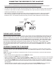

MODEL RVS304
Supplemental Installation Instructions for use with
Natural Gas Log Sets
NOTE: This kit is for both Natural Gas and LP Gas applications. For LP (Propane) Gas
installation, see additionall LP instructions packaged with necessary hardware.
DO NOT USE THE NATURAL GAS ORIFICE SUPPLIED WITH THIS KIT ON LP
(PROP ANE) GAS INSTALLATIONS! IMPROPER COMBUSTION WILL OCCUR!
IMPORTANT:
Read and follow ALL instructions carefully, as these supplemental Remote Controlled
Pilot Assembly instructions are to be used in conjunction with the General Installation
Instructions supplied with all Vented Natural Gas Log Sets.
National code Requirements mandate the use of a Safety Pilot Valve on all LP (Pro-
pane applications. These regulations MUST be followed on all installations of this type.
1
2
3
6
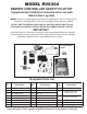
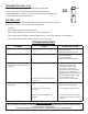
Part
No.
Description
4
5
7
8
Part
No.
Part
No.
Description Description
Remote Transmitter
Remote Receiver & Hardware
Gas Control Valve
Straight Flare Fitting, 3/8”
Thermocouple lead connection
Pilot Line Connection
Pilot Burner Assembly
Pilot Bracket
9
10
11
12
13
14
15
16
Sheet Metal Screw (1)
Machine Screw (2)
Nut (2)
Pilot Orifice Location (NG)
Heat Shield
Machine Screw 10 x 24 (2)
Lock Nut (3/8 NPT)
Street Elbow, 90 deg. (2)
17
18
Heat Shield, Receiver
18” Natural Gas Orifice
(Small Center Hole)
24” Natural Gas Orifice
(Large Center Hole)
19
20 Battery,
ransmitter 12v 21 Battery, T
Receiver AA (3)
REMOTE CONTROLLED SAFETY PILOT KIT
22
Thread Sealant
1
2
3
7
8
21
20
22
LP Conversion
Items
LP Burner Media
14
5
6
15
4 18
19
16
17
9
11
13
10
Illustrated Parts List
12