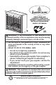
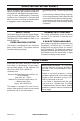
VENT-FREE GAS COMPACT FIREPLACE OWNER’S OPERATION AND INSTALLATION MANUAL MODEL VFF26NLMA PFS ® US WARNING: If the information in this manual is not followed exactly, a fire or explosion may result causing property damage, personal injury or loss of life. — Do not store or use gasoline or other flammable vapors and liquids in the vicinity of this or any other appliance. — WHAT TO DO IF YOU SMELL GAS • Do not try to light any appliance.
TABLE OF CONTENTS Safety......................................................... 3 Specifications............................................. 4 Qualified Installing Agency......................... 5 Product Features........................................ 5 Local Codes............................................... 5 Unpacking.................................................. 6 Product Identification.................................. 6 Water Vapor: A By-Product Of Unvented Room Heaters....................
SAFETY IMPORTANT: Read this owner’s manual carefully and completely before trying to assemble, operate, or service this heater. Improper use of this heater can cause serious injury or death from burns, fire, explosion, electrical shock and carbon monoxide poisoning. Failure to follow these instructions will void the warranty. Only a qualified installer, service agent, or local gas supplier may install and service this product.
SAFETY 1. Do not place Propane/LP supply tank(s) inside any structure. Propane/LP supply tank(s) must be placed outdoors. 2. This heater shall not be installed in a bedroom or bathroom. 3. This heater needs fresh air ventilation to run properly. This heater has an Oxygen Depletion Sensing (ODS) safety shutoff system. The ODS shuts down the heater if not enough fresh air is available. See Air for Combustion and Ventilation, pages 7. If heater keeps shutting off, see Troubleshooting, page 22. 4.
QUALIFIED INSTALLING AGENCY Only a qualified agency should install and replace gas piping, gas utilization equipment or accessories, and repair and equipment servicing.
UNPACKING 1. 2. 3. 4. 5 6. Remove top inner pack. Tilt carton so that heater is upright. Remove protective side packaging. Slide heater out of carton. Remove protective plastic wrap. Hold the screen, lift, and pull forward. 7. Remove log set by cutting plastic ties. 8. Carefully unwrap logs. 9. Check for any shipping damage. If heater or log is damaged, call our customer service department at 1-800-229-5647 10. Remove four screws and two bottom brackets.
AIR FOR COMBUSTION AND VENTILATION WARNING: This heater shall not be installed in a confined space or unusually tight construction unless provisions are provided for adequate combustion and ventilation air. Read the following instructions to insure proper fresh air for this and other fuel-burning appliances in your home. Today’s homes are built more energy efficient than ever. New materials, increased insulation and new construction methods help reduce heat loss in homes.
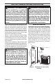
AIR FOR COMBUSTION AND VENTILATION Ventilation Air From Outdoors Provide extra fresh air by using ventilation grills or ducts. You must provide two permaVentilated Outlet Attic nent openings: one within 12" of the ceiling Air and one within 12" of the floor. Connect these Outlet items directly to the outdoors or spaces open Air To Attic to the outdoors. These spaces include attics and crawl spaces. Follow the National Fuel To Gas Code, ANSI Z223.
INSTALLATION IMPORTANT: Vent-free heaters add moisture to the air. Although this is beneficial, installing heater in rooms without enough ventilation air may cause mildew to form too much moisture. See Air for Combustion and Ventilation, pages 7. CHECK GAS TYPE Be sure your gas supply is right for your heater. Otherwise, call dealer where you bought the heater for proper type heater. CLEARANCES TO COMBUSTIBLES WARNING: You must maintain the minimum clearances.
INSTALLATION Fitting supplied with the product located in the hardware bag. Fitting part number: 160960-02 (straight) 160960-03 (elbow) Figure 5 - Supplied Fitting Insert Gas Fitting for Propane/LP Gas Insert Gas Fitting for Natural Gas FOR NATURAL GAS (NG) INSTALLATION: YELLOW 1. Remove the blue dust cover from the regulator. 2. Remove the metal cap installed over the NG regulator inlet.
INSTALLATION DO NOT try to remove the plungers from inside the regulator. The plunger will be pushed back as the fitting is installed. Back of Fireplace DO NOT use an off the shelf 3/8" NPT pipe plug. This will damage the plungers located inside the regulator. Make sure the type of gas being used is correct. Check to make sure the connection fitting is in the correct inlet on the regulator. Refer to Connecting to Gas Supply, page 13.
INSTALLATION 1. Frame in rough opening. Use dimensions shown in Figure 9 for the rough opening. If installing in a corner, use dimensions shown in Figure 10 for the rough opening. The height is 26 1/2", which is the same as the wall opening above. 2. Carefully set fireplace in front of rough opening with back of fireplace inside wall opening. 3. Attach gas line to fireplace gas regulator. See Connecting to Gas Supply, page 13. 4. Check all gas connections for leaks. See Checking Gas Connections, page 15.
INSTALLATION MANTEL Assemble and install your mantel at this time. See page 28 for mantel instructions. Mantel must be in place before you connect to the gas supply. CONNECTING TO GAS SUPPLY WARNING: A qualified service technician must connect heater to gas supply. Follow all local codes. WARNING: This appliance requires a 3/8" NPT (National Pipe Thread) inlet connection to the pressure regulator. WARNING: For natural gas, Never connect heater to private (non-utility) gas wells.
INSTALLATION Typical Inlet Pipe Diameters Use 3/8" black iron pipe or greater. Installation must include an equipment shutoff valve, union, and plugged 1/8" NPT tap. Locate NPT tap within reach for test gauge hook up. NPT tap must be upstream from heater (see Figure 12). IMPORTANT: Install an equipment shutoff valve in an accessible location. The equipment shutoff valve is for turning on or shutting off the gas to the appliance. For propane/LP installations, apply pipe joint sealant lightly to male threads.
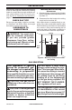
INSTALLATION CHECKING GAS CONNECTIONS WARNING: Test all gas piping and connections for leaks after installing or servicing. Correct all leaks at once. WARNING: Never use an open flame to check for a leak. Apply a noncorrosive leak detection fluid to all joints. If bubbles form, there is a leak. Correct all leaks at once. PRESSURE TESTING GAS SUPPLY PIPING SYSTEM Test Pressures In Excess Of 1/2 PSIG (3.5 kPa) 1.
INSTALLATION PRESSURE TESTING HEATER GAS CONNECTIONS 1. Open equipment shutoff valve (see Figure 17, page 15). Apply a noncorrosive leak 15, page 15). detection fluid to all joints. Bubbles forming show a leak. 2. Open main gas valve located on or near gas meter for natural gas or open pro- 5. Correct all leaks at once. pane/LP supply tank valve. 6. Light heater (see Lighting Instructions on 3. Make sure control knob of heater is in the page 18). Check all other internal joints OFF position. for leaks. 4.
INSTALLATION BATTERY INSTRUCTIONS CAUTION: Do not dispose of batteries in fire, batteries may explode or leak. Unscrew ignitor cap and install a AAA battery with the + pointing out. Replace cap. • • • • Battery is included. Remove battery when depleted. Only install or replace with a AAA battery. Be sure to observe proper polarity (+/-) when installing or replacing the battery. Damage due to improper battery installation may void the warranty on the product.
OPERATION LIGHTING INSTRUCTIONS WARNING: You must operate this heater with the screen in place. Make sure screen is installed before running heater. NOTICE: During initial operation of new heater, burning logs will give off a paper-burning smell. Orange flame will also be present. Open damper or window to vent smell. This will only last a few hours. 1. STOP! Read the safety information on page 17. 2. Make sure equipment shutoff valve is fully open. 3. Turn control knob clockwise to the OFF position. 4.
OPERATION THERMOSTAT CONTROL OPERATION The thermostatic control used on this model differs from standard thermostats. You set standard thermostats to a specific temperature such as 72 degrees. The thermostat used on this heater senses the room temperature. At times the room may exceed the set temperature. If so, the burner will shut off. The burner will cycle back on when room temperature drops below the set temperature. The control knob can be set to any comfort level between HIGH (5) and LOW (1).
INSPECTING BURNERS Natural Gas Shown Natural Gas Shown NG 3-3.5" WC LP 8-11" WC NG 3-3.5" WC LP 8-11" WC Approx. 3"-6" Above Top of Logs Figure 22 - Correct Pilot Flame Pattern (Natural Gas shown) Figure 23 - Incorrect Pilot Flame Pattern (Natural Gas shown) BURNER FLAME PATTERN Figure 24 shows a correct burner flame pattern. Figure 25 shows an incorrect burner flame pattern. If burner flame pattern is incorrect then: • turn heater off (see To Turn Off Gas to Appliance, page 19).
CARE AND MAINTENANCE CLEANING BURNER PILOT AIR INLET HOLE We recommend that you clean the unit every 2,500 hours of operation or every three months. We also recommend that you keep the burner tube and pilot assembly clean and free of dust and dirt. To clean these parts we recommend using compressed air no greater than 30 PSl. Your local computer store, hardware store, or home center may carry compressed air in a can. You can use a vacuum cleaner in the blow position.
TROUBLESHOOTING WARNING: If you smell gas: • Shut off gas supply. • Do not try to light any appliance. • Do not touch any electrical switch; do not use any phone in your building. • Immediately call your gas supplier from a neighbor’s phone. Follow the gas supplier’s instructions. • If you cannot reach your gas supplier, call the fire department. WARNING: Only a qualified service technician should service and repair heater. Turn off and let cool before servicing.
TROUBLESHOOTING Problem Possible Cause Corrective Action When ignitor button is 1. Ignitor electrode is posi- 1. Replace electrode. pressed in, there is no tioned wrong. Ignitor elecspark at ODS/pilot. trode is broken. 2. Ignitor electrode is not con- 2. Replace ignitor cable. nected to ignitor cable. 3. Ignitor cable is pinched or 3. Free ignitor cable if pinched wet. by any metal or tubing. Keep ignitor cable dry. 4 Broken ignitor cable. 4. Replace ignitor cable. 5. Bad piezo ignitor. 5.
TROUBLESHOOTING Problem Possible Cause Corrective Action Burner(s) does not light 1. Burner orifice is clogged. after ODS/pilot is lit. 1. Clean burner orifice (see Care and Maintenance, page 20) or replace burner orifice. 2. Burner orifice diameter is too 2. Replace burner orifice. small. 3. Inlet gas pressure is too low. 3. Contact local gas supplier. Delayed ignition of 1. Manifold pressure is too low. 1. Contact local gas supplier. burner(s). 2. Burner orifice is clogged. 2.
TROUBLESHOOTING Problem Possible Cause Corrective Action White powder residue 1. When heated, the vapors 1. Turn heater off when using forming within burner from furniture polish, wax, furniture polish, wax, carpet box or on adjacent walls carpet cleaners, etc., turn cleaner or similar products. or furniture. into white powder residue. Heater produces un- 1. Heater is burning vapors from 1. Ventilate room. Stop using wanted odors. paint, hair spray, glues, etc.
PARTS MODEL VFF26NLMA 4 6 3 5 7 1 2 11 8 12 13 14 9 26 www.sureheat.
PARTS MODEL VFF26NLMA This list contains replaceable parts for your heater. When ordering replacement parts, follow the instructions listed under Replacement Parts below.
MANTEL PRODUCT SPECIFICATIONS 21" cm 53.34 15" m 38.1 c 43.46 110.3 " 8 cm 39.33" 99.9 cm PACKAGE CONTENTS If a part is missing or damaged, call customer service at 1-800-229-5647 (exterior wood components are not replaceable). Item Description Qty A Top 1 B Panel 1 C Left Side Panel 1 D Right Side Panel 1 E Base 1 F Top Triangle Panel 1 G Backboard 2 H Set Square Support 1 F H A B G G C D E 28 www.sureheat.
MANTEL HARDWARE CONTENTS FF AA BB GG CC HH DD II Item EE AA BB CC DD EE FF GG HH II Description Hardware Package Cam Dowel Cam Lock Wall Anchor ST4 Screw 1 3/16" ST5 Screw 2 3/8" ST4 Screw 5/8" Connector Bracket White Key ST4 Screw 1 9/16" Part # HP006 PCAM-023 PCAM-023 ML066-01 GB/T 951 4×30 GB/T 950 5×60 GB/T 951 4×16 SJ002 ML067-01 GB/T 951 4×40 Qty 1 16 16 2 8 2 18 3 1 8 WARNING: When tightening screws, do not over tighten, this may cause threads to strip.
MANTEL ASSEMBLY INSTRUCTIONS 1. Insert 4) Cam Locks (BB) into Panel (B). Screw 4) Cam Dowels (AA) into the Left Side Panel (C) and the Right Side Panel (D). Attach Panel (B) into assembled frame (C, D) by tightening the Cam Locks (BB) as shown in Figure 29. AA B C BB D Figure 29 2. Insert 6) Cam Locks (BB) into the Left Side Panel (C) and the Right Side Panel (D). Screw 6) Cam Dowels (AA) into Base (E). Attach Base (E) into assembled frame by tightening the Cam Locks (BB) as shown in Figure 30.
MANTEL 3. Fasten the wood support brackets attached to the Left Side (C) and Right Side (D) Panels with 4) ST4Screw 1 9/16" (II) to the Base (E) as shown in Figure 31. C D II E Figure 31 For Corner Mantel, skip to step 8, page 33. 4. Insert 6) Cam Locks (BB) into assembled frame (B,C,D). Screw 6) Cam Dowels (AA) into Top (A). Attach Top (A) into assembled frame by tightening the Cam Locks (BB) as shown in Figure 32. A AA B BB C D Figure 32 200252-01A www.sureheat.
MANTEL 5. Fasten the wooden support brackets attached to the top of the mantel assembly to the Top (A) with 4) ST4 Screw 1 9/16" (II) as shown in Figure 33. A II Figure 33 6. After assembling the mantel, lift to the upright position. Carefully, push the fireplace insert from the front of the mantel as shown in Figure 34. 7. Position the fireplace to the desired location as shown in Figure 35. Wall Figure 35 Fireplace Insert Figure 34 32 www.sureheat.
MANTEL 8 . Turn the fireplace Top Panel (A) over. Using the 3 supplied Connector Brackets (GG), attach the Mantel Top (A) to the Top Triangle Panel (H) with 18) ST4 Screw 5/8" (FF) as shown in Figure 36. A FF H GG Figure 36 9. Insert 6) Cam Locks (BB) into Panel (B), the Left Upper Panel (C) and the Right Upper Panel (D). Screw 6) Cam Dowels (AA) into Top (A). Attach Top (A) into assembled frame by tightening the Cam Locks (BB) as shown in Figure 37. A AA B D BB Figure 37 200252-01A www.sureheat.
MANTEL 10. Fasten the wooden support brackets attached to the top of the mantel assembly to the Top (A) with 4) ST4 Screw 1 9/16" (II) as shown in Figure 38. A II Figure 38 11. Attach the left and right Backboard (G) trim pieces to the back of the fireplace with 8) ST4 Screw 1 3/16" (DD) as shown in Figure 39. G 34 DD Figure 39 www.sureheat.
MANTEL 12. After assembling the mantel, carefully lift to the upright position. Push the fireplace insert from the front of the mantel as shown in Figure 40. 14. Install the Set Square Support (H) to the holes drilled in step 13, with 2) ST5 Screws 2 3/8" (EE) as shown in Figure 42. This block is used to support the Top Triangle Panel (F). For thin walls, insert white key (HH) into wall anchor and push to “pop” open anchor wings.
WARRANTY KEEP THIS WARRANTY Model ________________________________ Serial No. _____________________________ Date Purchased ________________________ Keep receipt for warranty verification. IMPORTANT: We urge you to fill out your warranty information above. Complete with the entire serial number which can be found on the rating plate. Retain this manual for future reference. Always specify model and serial numbers when communicating with customer service.
FUEGO COMPACTA DE GAS SIN VENTILACIÓN MANUAL DE FUNCIONAMIENTO E INSTALACIÓN DEL PROPIETARIO MODELO VFF26NLMA PFS ® US ADVERTENCIA: Si la información contenida en este manual no se sigue al pie de la letra, se pueden producir un incendio o una explosión que podrían ocasionar daños a la propiedad, lesiones personales o la pérdida de la vida. — No guarde ni utilice gasolina u otros vapores y líquidos inflamables cerca de este aparato ni de cualquier otro.
TABLA DE CONTENIDOS Seguridad................................................. 39 Especificaciones....................................... 41 Agencia De Instalación Calificada............ 41 Características Del Producto.................... 42 Normas Locales....................................... 42 Desempaque............................................ 43 Identificación Del Producto ...................... 43 Vapor De Agua: Un Producto Derivado de Los Calentadores de Habitación Sin Ventilación................
SEGURIDAD IMPORTANTE: Lea este manual del propietario cuidadosa y completamente antes de intentar ensamblar, operar o dar servicio a este calentador. El uso inadecuado de este calentador puede causar daños a la propiedad, lesiones graves o la muerte por quemaduras, incendio, explosión, electrocución e intoxicación con monóxido de carbono. No seguir estas instrucciones anula la garantía.
SAFETY ADVERTENCIA: El calentador se calienta mucho durante la operación. Mantenga a niños y adultos alejados de las superficies calientes para evitar quemaduras o que la ropa se encienda. El calentador permanecerá caliente durante algún tiempo después de que se ha apagado. Permita que la superficie se enfríe antes de tocarla. ADVERTENCIA: Supervise cuidadosamente a los niños pequeños cuando estén en la habitación en la que se encuentra el calentador.
SEGURIDAD 16. Este calentador de leños está diseñado para no producir humo. Si pareciera que los leños producen humo, apague el calentador y llame a un técnico calificado. Nota: durante el primer uso, es posible que haya un poco de humo debido al curado de los leños y a la combustión de los residuos de fabricación. 17. No haga funcionar el calentador si alguno de los leños está roto.
CARACTERÍSTICAS DEL PRODUCTO PILOTO DE SEGURIDAD CONTROL DEL CALOR POR TERMOSTATO El calentador posee un piloto que cuenta con un sistema de apagado de seguridad por medio de un sensor de agotamiento de oxígeno (ODS). El sensor de agotamiento de oxígeno del piloto apaga el calentador si no hay suficiente cantidad de aire fresco. El control apaga y enciende el quemador de forma automática por ciclos para mantener una temperatura ambiente deseada.
DESEMPAQUE 1. Retire la parte superior del empaque interno. 2. Incline la caja de manera que el calentador quede en posición vertical. 3. Retire el empaque lateral de protección. 4. Saque el calentador de la caja. 5. Retire el empaque de plástico de protección. 6. Sostenga la malla, levante y tire hacia adelante. 7. Retire el juego de leños cortando los amarres de plástico. 8. Retire cuidadosamente la envoltura del leños. 9. Verifique que no haya daños en el transporte.
AIRE PARA COMBUSTIÓN Y VENTILACIÓN ADVERTENCIA: Este calentador no debe instalarse en un espacio confinado ni en una construcción inusualmente sellada, a menos que se hayan tomado las medidas necesarias para proporcionar el aire adecuado para la combustión y la ventilación. Lea las instrucciones siguientes para asegurarse de que su hogar cuente con la cantidad adecuada de aire fresco para éste y otros aparatos que queman combustible.
AIRE PARA COMBUSTIÓN Y VENTILACIÓN Aire del exterior para ventilación Proporcione aire fresco adicional mediante el uso de rejillas o conductos de ventilación. Debe haber dos aberturas permanentes: una a 30.48 cm (12") del techo y otra a 30.48 cm (12") del suelo. Conecte estos elementos directamente al exterior o a los espacios que estén abiertos al exterior. Estos espacios incluyen áticos y espacios debajo del piso de la casa. Consulte el Código Nacional de Gas Combustible, ANSI Z223.
INSTALACIÓN PRECAUCIÓN: Este calentador crea corrientes de aire caliente. Estas corrientes mueven el calor hacia la superficie de las paredes próximas al calentador. La instalación del calentador cerca de paredes con recubrimientos de vinilo o tela, o la operación del calentador en lugares donde existan impurezas en el aire (como humo de tabaco, velas aromáticas, líquidos limpiadores, lámparas de aceite o de queroseno, entre otros), puede manchar las paredes o producir olores.
INSTALACIÓN SELECCIÓN DE GAS Este aparato viene ajustado de fábrica para gas propano/ LP. No se requieren cambios para la conexión a propano/ LP. Sólo un instalador o técnico de servicio calificado puede realizar la selección de gas y la conexión al suministro de gas. PRECAUCIÓN: Dos instalaciones de líneas de gas, al mismo tiempo están prohibidos.
INSTALACIÓN PARA GAS NATURAL (NG) INSTALACIÓN: AMARILLO 1. Retire la cubierta de polvo azul del regulador. 2. Retire la tapa metálica instalada sobre la entrada del regulador NG. Tapa de metal 3. Instale la tapa de metal sobre entrada del regulador LP/propano. Esto evitará que los residuos fuera del regulador. Tapa de metal NO QUITE Amarillo Gas Natural émbolo Instale Gas Fitting Aquí Utilice solamente el tapón suministrado en el regulador. No utilice un fuera el tapón del tubo estante.
INSTALACIÓN AVISO: Las temperaturas de las superficies de paredes y repisas para chimenea adyacentes aumentan durante el uso. Las paredes y las repisas para chimenea ubicadas sobre la cámara de combustión pueden calentarse al tacto. Si la instalación es la correcta, estas temperaturas cumplen el requisito de la norma nacional para el producto. Respete todas las distancias mínimas que se indican en este manual (consulte la figura 8).
INSTALACIÓN ENSAMBLAJE DE LA CAMPANA PRECAUCIÓN: No use la chimenea sin la campana. 1. La campana de la chimenea se coloca sobre el paquete interior incluido. 2. Retire la parte superior de la cámara de combustión desatornillando los 2 tornillos ubicados en cada extremo (consulte la figura 11). 3. Inserte la campana por la parte superior del tablero de aislamiento de calor (consulte la figura 11). Fije la campana con 3 tornillos. 4.
INSTALACIÓN CONEXIÓN AL SUMINISTRO DE GAS ADVERTENCIA: Una persona de servicio capacitada debe conectar el calentador al suministro de gas. Siga todas las normas locales. ADVERTENCIA: Este aparato requiere una conexión de entrada tipo NPT (rosca de tubería nacional) de 3/8" al regulador de presión. ADVERTENCIA: Para gas natural, nunca conecte el calentador a pozos de gas privados (que no sean de servicio público). Este gas se conoce comúnmente como gas de pozo.
INSTALACIÓN Conexión del medidor de prueba* Diámetros usuales de tubería Niple para tubería Unión de entrada con rosca de 3/8" terminal con tipo NPT Utilice tuberías de hierro negro de conexión a 3/8" o más grandes. La instalación tierra Válvula de debe incluir la válvula de cierre del cierre del Unión T equipo, la unión y el tapón con rosequipo * Buje ca NPT de 1/8".
INSTALACIÓN REVISIÓN DE LAS CONEXIONES DE GAS ADVERTENCIA: Después de instalar el calentador o de darle servicio, pruebe todas las conexiones y tubos de gas de la unidad, tanto internas como externas, en busca de fugas. Repare todas las fugas inmediatamente. ADVERTENCIA: Nunca use una llama al descubierto para verificar si hay fugas. Aplique líquido no corrosivo para detectar fugas en todas las uniones. La formación de burbujas indicará una fuga. Repare todas las fugas inmediatamente. 5.
INSTALACIÓN COMPROBACIÓN DE LA PRESIÓN DE LAS CONEXIONES DE GAS DEL CALENTADOR 1. Abra la válvula de cierre del equipo (conpágina 53). Aplique en todas las uniones sulte la figura 12, página 53). algún líquido de detección de fugas que 2. Abra la válvula principal localizada en no sea corrosivo. La formación de burbuo cerca del medidor de gas si usa gas jas indicará una fuga. natural, o abra la válvula del tanque de 5. Repare todas las fugas inmediatamente. suministro de gas propano/LP. 6.
INSTALACIÓN INSTRUCCIONES PARA LAS BATERÍAS PRECAUCIÓN: No tire las pilas al fuego, pueden explotar o tener fugas. • Las baterías están incluidas. • Retire la batería cuando se agoten. • Sólo instale o sustituya con una batería AAA. • Asegúrese de observar la polaridad correcta (+ / -) al instalar o reemplazar la batería. Los daños debidos a una instalación incorrecta de la batería puede invalidar la garantía del producto.
FUNCIONAMIENTO INSTRUCCIONES DE ENCENDIDO ADVERTENCIA: Debe operar este calentador con la rejilla colocada en su lugar. Asegúrese de que la rejilla esté instalado antes de hacer funcionar el calentador. AVISO: Durante el funcionamiento inicial de un calentador nuevo, los leños despedirán un olor a papel quemado. También habrá llamas anaranjadas. Abra el regulador del tiro o una ventana para ventilar el olor. Esto durará solamente unas horas. 1. ¡ALTO! Lea la información de seguridad en la página 55. 2.
FUNCIONAMIENTO Nota: si el piloto se apaga, repita los pasos 7 al 10. Este calentador tiene un sistema de bloqueo de seguridad. Espere un (1) minuto antes de encender el piloto nuevamente. 8. Gire la perilla de control en sentido contrario al de las manecillas del reloj para el nivel de calefacción deseado. El quemador principal deberá encenderse. Fije el mando de control a cualquier nivel de calor entre HI (5) y LO (1).
INSPECCIÓN DE LOS QUEMADORES IMPORTANTE: El propietario debe revisar frecuentemente los patrones de la llama del piloto y de la llama del quemador. Patrones de llama incorrectos indican la necesidad de limpieza o servicio de mantenimiento (consulte Cuidado y mantenimiento, página 59). ADVERTENCIA: Sólo una persona de servicio capacitada debe repararlo o darle servicio. Esto incluye el mantenimiento requerido, refacciones o alteración de componentes.
CUIDADO Y MANTENIMIENTO ADVERTENCIA: Apague el calentador y deje que se enfríe antes de darle mantenimiento. Sólo una persona de servicio capacitada debe repararlo o darle servicio. PRECAUCIÓN: Debe mantener limpias las áreas de control, el quemador y las vias de circulación de aire del calentador. Inspeccione estas áreas del calentador antes de cada uso. Haga que una persona de servicio calificada inspeccione el calentador una vez al año.
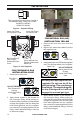
CUIDADO Y MANTENIMIENTO ODS/PILOTO PRECAUCIÓN: Nunca utilice un alambre, aguja u objetos parecidos para limpiar el piloto/ ODS. Esto puede dañar la unidad de piloto/ODS. Quemador de Electrodo del encendedor gas natural Termopar Quemador de Gas Propano/LP Utilice una aspiradora, aire comprimido o un cepillo pequeño, de cerdas suaves para Orificio de entrada de limpiarlos.
SOLUCIÓN DE PROBLEMAS IMPORTANTE: Si hace funcionar el calentador donde existen impurezas en el aire se pueden producir olores. Los productos de limpieza, pintura, solventes de pintura, humo de cigarro, cementos y pegamentos, alfombras o textiles nuevos, etc., producen gases. Estos gases se pueden mezclar con el aire que se utiliza para la combustión y producir olores. Nota: todos los puntos para solución de problemas se listan en orden de funcionamiento.
SOLUCIÓN DE PROBLEMAS Problema Causa Posible Acción Correctiva Cuando se presiona el 1. El suministro de gas está 1. Abra el suministro de gas o la botón del encendedor, cerrado o la válvula de cierre válvula de cierre del equipo. hay chispa en el piloto/ del equipo está cerrada. ODS pero no se en- 2. La perilla de control no se 2. Presione la perilla de control ciende. presionó del todo al pulsar del todo al pulsar el botón el botón de encendido. de encendido. 3. Quedó aire en las líneas 3.
SOLUCIÓN DE PROBLEMAS Problema Causa Posible Acción Correctiva El quemador no se en- 1. El orificio del quemador está 1. Limpie el quemador (consulciende después de que el tapado. te Cuidado y mantenimiento, piloto/ODS se enciende. en la página 59) o remplace el quemador. 2. El diámetro del orificio del que- 2. Remplace el orificio del quemador es demasiado pequeño. mador. 3. La entrada de la presión de 3. Contacte a su proveedor gas es demasiado baja. local de gas. Encendido demorado del 1.
SOLUCIÓN DE PROBLEMAS Problema Causa Posible Acción Correctiva El calentador produce un 1. Se giró la perilla de control a 1. Gire la perilla de control a la silbido cuando el quemala posición HI (Alto) cuando posición LO (bajo) y deje que dor está encendido. el quemador estaba frío. se caliente durante un minuto. 2. Hay aire en la tubería de gas. 2. Haga funcionar el quemador hasta que se elimine el aire de la tubería. Pida a la empresa proveedor local de gas que revise la línea de gas. 3.
SOLUCIÓN DE PROBLEMAS Problema Causa Posible Acción Correctiva Hay olor a gas incluso 1. Fugas de gas. Consulte la 1. Localice y repare todas las cuando la perilla de conanotación de Advertencia al fugas (consulte Revisión de trol está en la posición inicio de la página 60. las conexiones de gas, en la OFF (apagado). página 53). 2. La válvula de control está 2. Remplace la válvula de condefectuosa. trol. Se observa humedad 1. No hay suficiente aire para 1.
PIEZAS MODELO VFF26NLMA 4 6 3 5 7 1 2 11 8 12 13 14 9 66 www.sureheat.
PIEZAS MODELO VFF26NLMA Esta lista contiene las piezas remplazables utilizadas en el calentador. Al hacer un pedido de piezas, siga las instrucciones listadas en Piezas de repuesto en la página 65 de este manual. Art. Pieza # Descripción Cant.
REPISA DE CHIMENEA ESPECIFICACIONES DEL PRODUCTO 15" m 38.1 c 21" cm 53.34 43.46 110.3 " 8 cm 39.33" 99.9 cm CONTENIDO DEL PAQUETE Si una pieza no se encuentra o está dañado, llame al servicio al cliente al 1-800-229-5647 (los componentes exteriores de madera no son reemplazables). Art. A B C D E F G H Descripción Cant.
REPISA DE CHIMENEA CONTENIDOS HARDWARE FF AA BB GG CC HH DD II Art. EE AA BB CC DD EE FF GG HH II Descripción Paquete de hardware Espiga de leva Cerrojo de leva anclaje de pared ST4 Tornillo 1 3/16" ST5 Tornillo 2 3/8" ST4 Tornillo 5/8" Conector Soporte Llave blanco ST4 Screw 1 9/16" Pieza # HP006 PCAM-023 PCAM-023 ML066-01 GB/T 951 4×30 GB/T 950 5×60 GB/T 951 4×16 SJ002 ML067-01 GB/T 951 4×40 Cant 1 16 16 2 8 2 18 3 1 8 ADVERTENCIA: No apriete demasiado los tornillos.
REPISA DE CHIMENEA INSTRUCCIONES DE ENSAMBLAJE 1. Inserte los 4) cerrojos de leva (BB) en la Panel (B). Atornille 4) Espigas de leva (AA) en el Panel lateral izquierdo (C) y el Panel lateral derecho (D). Coloque la Panel (B) en la estructura ensamblada (C, D) apretando la los Cerrojos de leva (BB) como se muestra en la Figura 29. AA B C BB D Figura 29 2. Inserte 6) cerrojo de levas (BB) en el panel lateral izquierdo (C) y el panel lateral derecho (D). Atornille 6) Espiga de levas (AA) en la base (E).
REPISA DE CHIMENEA 3. Fije los soportes de madera colocada en el lateral izquierdo (C) y el lateral derecho (D) paneles con 4) ST4 Tornillo 1 9/16" (II) a la Base (E) como se muestra en la Figura 31. C D II E Figura 31 Para ángulo repisa de chimenea, vaya al paso 8, página 33. 4. Inserte 6) Cerrojo de levas (BB) en el marco ensamblado (B, C, D). Atornille 6) Espiga de levas (AA) en la parte superior (A).
REPISA DE CHIMENEA 5. Fije los soportes de apoyo de madera unidos a la parte superior del montaje de la repisa a la parte superior (A) con 4) ST4 Tornillo 1 9/16" (II) como se muestra en la Figura 33. A II Figura 33 6. Tras el montaje de la repisa de chimenea, elevar a la posición vertical. Con cuidado, empuje el relleno de la chimenea desde el frente de la repisa de chimenea, como se muestra en la Figura 34. 7. Coloque la chimenea a la ubicación deseada, como se muestra en la Figura 35.
REPISA DE CHIMENEA 8. Gire el parte superior chimenea (A) más. Usando el 3 suministrado Conector Soportes (GG), ajuste la Repisa superior (A) al panel superior del triángulo (H) con 18) ST4 Tornillo de 5/8" (FF), como se muestra en la Figura 36. A FF H GG Figura 36 9. Inserte 6) Cerrojo de levas (BB) en el panel (B), el panel superior izquierdo (C) y el panel superior derecho (D). Atornille 6) Espiga de levas (AA) en la superior (A).
REPISA DE CHIMENEA 10. Fije los soportes de apoyo de madera unidos a la parte superior del montaje de la repisa a la parte superior (A) con 4) ST4 Tornillo 1 9/16" (II) como se muestra en la Figura 38. A II Figura 38 11. Coloque el tablero piezas especiales izquierdo y derecho (G) a la parte posterior de la chimenea con 8) Tornillo ST4 1 3/16" (DD) como se muestra en la Figura 39. G 74 DD Figura 39 www.sureheat.
REPISA DE CHIMENEA 12. Tras el montaje de la repisa de chimenea, elevar a la posición vertical. Con cuidado, empuje el relleno de la chimenea desde el frente de la repisa de chimenea, como se muestra en la Figura 40. 14. Instale el soporte escuadra (H) en los orificios perforados en el paso 13, con 2) ST5 Tornillos 2 3/8" (EE) como se muestra en la Figura 41. Este bloque se utiliza para apoyar el panel superior del triángulo (F).
GARANTÍA GUARDE ESTA GARANTÍA Modelo___________________________________ Número de serie___________________________ Fecha de compra __________________________ Conserve su recibo para la verificación de la garantía. IMPORTANTE: Le pedimos que complete la información de su garantía antes mencionada. Completo con todo el número de serie que se puede encontrar en la placa de características. Conserve este manual para futuras consultas.