SBC6300x ARM9 Based Single Board Computer WinCE Development Guide Version 1.
Copyright Statement: SBC6300x and its related intellectual property are owned by Shenzhen Embest Technology Co., Ltd. Shenzhen Embest Technology has the copyright of this document and reserves all rights. Any part of the document should not be modified, distributed or duplicated in any approach and form without prior written permission issued by Embest Technology Co., Ltd Revision History: Version Date Description 1.0 24/10/2009 Original Version 1.1 26/02/2013 First Revision 1.
Table of Contents SBC6300X WinCE 6.0 User Manual. Error! Bookmark not defined. Chapter I. Introduction of the ManualError! Bookmark not defined. 1.1 Terms and definitions ................................................................. 1 1.2 Disclaimer ...................................... Error! Bookmark not defined. Chapter II. Introduction of WinCE 6.0 system ......................... 2 2.1 Image files related to SBC6300X WinCE 6.0 system ......................... 2 2.
1 Overview This Manual mainly expounds the burning of WinCE 6.0 system image files of the SBC6300X main board and system customization based on the SBC6300X WinCE 6.0 BSP. 1.1 Terms and definitions Development Workstation: Development Workstation means X86 PC installed with Windows XP operating system, Microsoft Visual Studio 2005 and Windows Embedded CE 6.0 development environment. This PC must have a serial port and a USB port.
2 Introduction to the WinCE 6.0 system 2.1 Image files related to the SBC6300X WinCE 6.0 system If the WinCE system is customized using the SBC6300X WinCE 6.0 BSP that we provide and the compilation is successfully finished, the system will generate FIRSTBOOT.bin, 6 image EBOOT.bin, files, i.e.: NK.bin , FIRSTBOOT.nb0, EBOOT.nb0, NK.nb0, of which 4 files are usually used in burning processes, i.e.: FIRSTBOOT.nb0, EBOOT.nb0, NK.nb0, NK.bin. The files generated in .
Figure 1: Booting Flowchart 2.2.1 Principles for booting the SBC6300X WinCE 6.0 system from DataFlash After power on, the system inside the CPU ROMBOOT will automatically copy the FIRSTBOOT image (the first-level user booting code) from the SPI DataFlash 0x00000000 address to the SRAM inside the CPU and execute it.
SPI NAND flash 0x00000000 address to the SRAM inside the CPU and execute it. FIRSTBOOT’s role is to initialize SDRAM memory, SPI NAND , and copy EBOOT, the second-level user booting code from the NAND Flash 0x00020000 address to SDRAM on the SBC6300X main board and execute it; FIRSTBOOT also copies the Logo from the NAND flash 0x00080000 address of the SBC6300X main board to SDRAM.
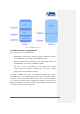
Figure 2: DataFlash Structure 2.3.2 When booted from NAND flash If you choose to boot from NAND flash: FIRSTBOOT is located at the beginning of the 0x00000000 address of the NAND Flash, the capacity of FIRSTBOOT is 4KB; EBOOT is located at the beginning of the 0x00020000 address of the NAND flash, the capacity of EBOOT is 200KB; The Logo is saved at 0x00080000 of the NAND Flash; WinCE system images are located in NAND Flash in an area of 40MB starting from the 0x00200000 address.
Figure 3: NAND Flash Structure Page | 6
3 Burning a WinCE System 3.1 Introduction to Burning System Image Files The SBC6300X WinCE 6.0 BSP supports two burning modes: 1. Burn FIRSTBOOT, EBOOT and WinCE system image NK using the SAM-BA software provided by ATMEL; 2. Connect VS2005 WinCE 6.0 development environment installed on client development workstation or other TFTP servers (e.g.: CEDownload.exe) to the SBC6300X main board, burn WinCE system image files NK via net cable using EBOOT on the SBC6300X (the EBOOT on the SBC6300X WinCE 6.
with the default path and configuration of the program. After the installation is complete, you will see the SAM-BA v2.8 icon on the desktop: Figure 4: SAM_BA Icon 3.2.2 Burning a system image using SAM-BA software 1. Make sure the three-way DIP switch is set to the OFF state and make sure there is no SD card in the SD slot of the SBC6300X. 2. Connect the USB device port (J9) of the SBC6300X to the USB Host of the development workstation using the supplied USB cable. 3.
Figure 6: SAM-BA Main Interface 7. Set the boards second and third DIP switches to the ON state then configure the software as shown above (under the DataFlash AT45DB/DCB tab). 8. Select Enable DataFlash (SPI0 CS0) in the Scripts box, and click the Execute button to enable SPI DataFlash on the SBC6300X main board.
Figure 7: SAM-BA Interface After DataFlash is Enabled 9. As shown above, select Send Boot File in the Scripts menu and click the Execute button.
10. As shown below, select the FIRSTBOOT_SPIDATAFLASH.nb0 file under the directory \03 WinCE 6.0 Kit\00 Image\ in the SBC6300X CD. In the open file dialog box click the open button, SAM-BA will automatically start burning the FIRSTBOOT_SPIDATAFLASH.nb0 file to the beginning of the 0x00000000 address of SPI DataFlash on the SBC6300X main board. Figure 9: Selecting File 11.
Figure 10: SAM-BA Main Interface 12. Enter the address 0x5000 in the Address field in the Download/Upload File section, select EBOOT_SPIDATAFLASH.nb0 file under the path \03 WinCE 6.0 Kit\00 Image\ on the SBC6300X CD in the Send File Name text box. Then click the Send File button in the Download/Upload File area, the software will automatically start burning EBOOT_SPIDATAFLASH.nb0 file to the beginning of the 0x00005000 address of SPI DataFlash on the SBC6300X main board.
Figure 11: Information to be Entered into SAM-BA 13.
Figure 12: Burning Successful 14. As shown below, enter the address 0x100000 in the Address field in the Download/Upload File area, select the Logo.bin file under the path \03 WinCE 6.0 Kit\00 Image\ on the SBC6300X CD in the Send File Name text box. Then click the Send File button in the Download/Upload File area. The software will automatically start burning the Logo.bin file to the beginning of the 0x00100000 address of SPI DataFlash on the SBC6300X main board.
Figure 13: SAM-BA Logo Settings 15. As shown below, select the NAND Flash tab. In the Scripts menu select Enable NAND Flash, and click the Execute button to enable NAND Flash on the SBC6300X main board.
Figure 14: Enabling NAND Flash 16.
Figure 15: Operation Successful 17. Select the SBC6300X CD \03 WinCE 6.0 Kit\00 Image \NK.nb0 file in the Send File Name area, then click the Send File button in the Download/Upload File section. The software will start burning the NK.nb0 file to the beginning of the 0x00200000 address of the NAND Flash on the SBC6300X main board.
Figure 16: SAM-BA NK.nb0 Settings 18. After the burning is successful, the interface (below) will appear. It takes 3-10 minutes to burn the NK.nb0 file.
Figure 17: Burning was Successful 3.3 Booting from NAND Flash 3.3.1 Burn SBC6300X system image through SAM-BA software 1. For installation of the SAM-BA software please refer to Section 3.2.1 , and finish steps 1-6 referring to Section 3.2.2. 2. Set the core board second DIP switch to the ON state. Then as shown below, select the NAND Flash tab in the software window.
Figure 18: SAM-BA NAND Flash Tab 3. In the Scripts menu, select Enable NAND Flash, and click the nearby Execute button to enable NAND flash on the SBC6300X main board.
Figure 19: NAND Flash Enabled 4. As shown below in the Scripts menu, select Erase All and click the Execute button; the software will automatically erase the entire NAND flash.
Figure 20: Erasing NAND Flash 5.
Figure 21: NAND Flash Erased 6. Select the Send Boot File button in the Scripts menu and click the Execute button. An open file dialog box as shown below will appear.
Comment [ML2]: Chinese Figure 22: Open File Dialog Box 7. As shown below, select the FIRSTBOOT_NAND.nb0 file under the path on the SBC6300X CD in the open file dialog box, then click the Open button. The software will \03 WinCE 6.0 Kit\00 Image\ automatically start burning the FIRSTBOOT_NAND.nb0 file to the beginning of the 0x00000000 address of the NAND Flash on the SBC6300X main board.
Figure 23: File Selection 8. After the burning is successful, the interface (below) will appear.
Figure 24: Burning Successful 9. As shown in the following image, enter the address 0x20000 in the Address: field. Select the SBC6300X CD \03 WinCE 6.0 Kit\00 file in the text box Send File Name:, then click the Send File button. The software will start burning the Image \EBOOT_NAND.nb0 EBOOT_NAND.nb0 file to the beginning of the 0x20000 address of the NAND Flash on the SBC6300X main board.
Figure 25: Burning EBOOT_NAND.nb0 10. After the burning is successful, the following interface will appear.
Figure 26: Burning Successful 11. As shown below, enter the address 0x80000 in the Address field. Select the SBC6300X CD \03 WinCE 6.0 Kit\00 Image \Logo.bin file in the Send File Name box, then click the Send File button. The software will start burning the Logo.bin file to the beginning of the 0x80000 address of the NAND flash on the SBC6300X main board.
Figure 27: Burning Logo.bin 12. As shown below, enter 0x00200000 in the address field in the software window; select the file \03 WinCE 6.0 Kit\00 Image \NK.nb0 (on the CD) in the Send File Name box, then click the Send File button. The software will start burning the NK.nb0 file to the beginning of the 0x00200000 address of the NAND Flash on the SBC6300X main board.
Figure 28: Burning NK.nb0 13. After the burning is successful, the following interface will appear. It takes 3-10 minutes to burn the NK.nb0 file.
Figure 29: Burning Successful Page | 31
4 Booting the WinCE 6.0 system 1. Refer to section 3; select the option to boot from DataFlash or NAND flash then burn the WinCE 6.0 system image files. 2. Set the power SWITCH to the ON state, the WinCE system will be booted. Enter the WinCE 6.0 system, the TFTLCD will first display the calibration touch screen as shown below.
5 System Customization Based on the WinCE 6.0 BSP Note: To develop a Windows Embedded CE 6.0 operating system using the SBC6300X BSP, you need setup a Windows Embedded CE 6.0 development workstation. This Manual assumes that the Windows Embedded CE 6.0 development workstation software has been installed on Drive F, e.g. the installation path for Windows Embedded CE 6.0 is [F:\WINCE600]. 5.1 Installation of the WinCE 6.0 BSP Unzip the archive located in: SBC6300X CD\03WinCE6.0Kit\01BSP\SBC6300X.
Figure 30: Starting a New Project 2. Select Platform Builder for CE 6.
3. Click the OK button, the system will progress to the next step of the Windows Embedded CE 6.0 OS Design Wizard. Figure 32: OS Design Wizard 4.
5. Click the Next button and select PDA Device in the newly opened Design Templates window: Figure 34: Select Design Template 6.
7. Click Next to open the Applications & Media window, add Internet Explorer 6.0 (under the Internet Browser checkbox) and WordPad in addition to the preselected default options: Figure 36: Add IE 6 and WordPad 8. Click the Next button to open Networking & Communications, remove Personal Area Network(PAN)->Bluetooth and Personal Area Network(PAN)->IraDA from the existing default options.
9. Click the Next button, then click finish in the OS Design Project Wizard Complete window shown below: Figure 38: Wizard Complete 10. Click Acknowledge to finish the initial customization of the WinCE 6.0 OS.
11. Tick the following options under Items Support View->SBC6300X->Core View->other OS->CEBASE->Core OS windows->Catalog Services->USB HOST in the Catalog Items window. USB Function Driver USB Host Support USB Human Input Device (HID) Class Driver->USB HID Keyborad and Mouse USB Storage Class Driver Figure 40: Adding USB Host Support 12.
TCP/IPv6 Support Continue to add the following options: Core OS->CEBASE->File Systems and Data Store->Storage Manager->Storage Manager Control Panel Applet Core OS->CEBASE->International->Locale Specific Support-> Chinese (Simplified) ->Fonts->SimSun&NsimSun(Choose 1)->SimSun&NsimSun Core OS->CEBASE->International->Locale Specific Support-> Chinese Specific Support-> Chinese (Simplified) ->GB1803030 Data ConverterCore OS->CEBASE->International->Locale (Simplified) -> Monotype Imaging
Figure 42: Open Properties 15. Tick Enable eboot space in memory (IMAGE=1) in Build Options, as below, click OK to finish editing the compilation settings. Figure 43: Enable EBOOT Space in Memory 16. Tick the driver of the module you need SBC6300X main board, in View->Other Party->SBC6300X:ARMV4I window->Catalog Items View->SBC6300X->Third in VS2005.
Figure 44: Select USB Storage Class Driver 17. Click Build->Advanced compiling: Build Commands->Sysgen in VS2005 to start Figure 45: Start Compiling 18. As the compilation may take a long time (depends on the hardware of the development workstation), please wait.
the system compilation is successful, VS2005 will export the following information: Figure 46: System Compilation Successful 19. The moment 6 WinCE 6.0 image files, i.e.: EBOOT.nb0, NK.nb0, FIRSTBOOT.bin, generated EBOOT.bin, FIRSTBOOT.nb0, will NK.bin, under be the F:\WINCE600\OSDesigns\SBC6300X\SBC6300X\RelDir\SBC6300X_ARMV4I_Releas\f older. 5.2 WinCE 6.0 BSP Driver Modules After the SBC6300X WinCE 6.
Module Function Buzzer driver. Display driver. Ethernet driver. GPIO driver. I2C driver. I2C EEPROM driver. IO driver. IO key driver. DM9000 driver 6X6 matrix keyboard driver PWM driver. SD card SDIO driver. AT91SAM9263 serial driver TFTLCD driver Touch screen driver.
Module Function USB device driver. USB host driver. Bootloader Hive registry. NAND Flash driver. SD card 4 cable SPI driver. Note: SD card SDIO driver and SD card 4 cable SPI driver can only be selected once.
Appendix 1: ESD Precautions & Handling Procedures Please note that the board comes without any case/box and all components are exposed. Therefore, extra attention must be paid to ESD (electrostatic discharge) precautions. To effectively prevent electrostatic damage, please follow the steps below: Avoid carpets in cool, dry areas. Leave development kits in their anti-static packaging until ready to be installed.
Appendix 2: Technical support & Warranty Embest Technology Co., Ltd. established in March of 2000, is a global provider of embedded hardware and software. Embest aims to help customers reduce time to market with improved quality by providing the most effective total solutions for the embedded industry.
Customers encounter issues related to their own applications. Customers experience problems caused by unauthorised alteration of our software source code 2.2 Maintenance service clause 1. Product warranty will commence on the day of sale and last 12 months provided the product is used under normal conditions 2.
3. Within the period of warranty, the cost for sending products to Embest should be paid by the customer. The cost for returning the product to the customer will be paid by Embest. Any returns in either direction occurring after the warranty period has expired should be paid for by the customer. 4. Please contact technical support with any repair requests. Note: Embest Technology will not take any responsibility for products returned without the prior permission of the company. 2.
Driver development based on Embest embedded platforms for devices such as: serial ports, USB interface devices, and LCD screens. Control system transplantation, BSP driver development, API software development. Other value added services including supply of power adapters and LCD parts. Other OEM/ODM services. Technical training. Please contact Embest with any technical support queries: http://www.embest-tech.com/contact-us.