
User manual

Page | 11
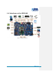
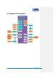
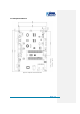
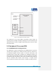
2 Introduction to Hardware
This chapter will help you learn about the hardware composition of the
MINI8510 core board by briefly introducing CPU, peripheral ICs and pin
definitions of various interfaces on the product (MINI8510+Expansion
board).
2.1 CPU Introduction
The MINI8510 core board uses the DM3730 – TI’s 45-nm
high-performance processor with low power and enhanced digital media
processing capability. The CPU has a 1GHz Cortex-A8 core and an 800MHz
TMS320C64+ DSP core, and also integrates a 3D graphics processing unit,
an imaging and video accelerator and USB 2.0, making it capable of 720p
video coding and decoding.
2.1.1 Clock
The clock signals of the DM3730 include sys_32k, sys_altclk, sys_clkout1,
sys_clkout2, sys_xtalout, sys_xtalin and sys_clkreq, among which:
sys_32k: the frequency is 32 KHz, generated by the TPS65930
power management chip and used for low-frequency calculation;
low-power mode is enabled through sys_32k pin.
sys_xtalou and sys_xtalin: are system input clocks with a
frequency of 26MHz and are used to provide primary clocks for
DPLLs and other modules.
2.1.2 Reset
Reset signal is determined by SYS_NRESPWRON of the CPU; a low level
validates resetting.
2.1.3 General Interfaces
General interfaces include 6 sets of GPIOs, each of which provides 32
dedicated GPIO pins, and therefore the total pin number of GPIOs can be
up to 192 (6×32). These pins can be configured for different applications
such as data input/output (driver), keypad interface and terminal control.