
- Emc Power Supply User Manual

16
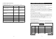
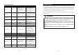
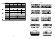
5.4 Default settings at the factory
On the LCD display you will find several of the UPS parameters to select.
Default settings are as follows:
Settings Selection Factory default
Output Voltage Setting 208/220/230/240 Vac 230V (FOR HV series)
Input/Bypass Voltage
±10%
+10/-15%
+15/-20%
+10/-15%
Input/Frequency
±2%
±5%
±7%
±5%
HE Mode Setting On/Off Off
Free Run Mode On/Off On
Bypass Enable/Disable at free run mode Disable/Enable Disable
Alarm silence On/Off Off
Site wiring alarm Enable/Disable Disable
External Battery pack setting 0, 1, 2 0
You may change default settings, but we recommend that this is done after installation and
before starting up loads. Read UPS configurations in chapter 7.2 for more information.
17
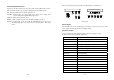
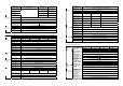
6. Computer and alarm connections
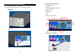
At the back of the UPS is an interface allowing direct communication with your computer
system, the location of which can be found in figure 4. There is a RS232 serial data
interface, one USB data interface and an emergency power off switch supplied. However,
the RS232 port cannot be used when the USB interface is in use.
In addition there is an optional interface slot that allows you to install different
communications cards. It can be used parallel with either the RS232 or USB ports.
Currently there are two cards available for the optional interface slot. An SNMP/WEB
card allows management and monitoring over a network or internet, and the AS/400 card
allows voltage free relay contacts. Your local dealer will have more information about
these option cards.
Connecting the UPS to a Computer
The communication device for the UPS and PC comes as a complete package with power
management software. Only the communication cable provided with UPS may be used to
connect to your computer, which is accomplished through the UPS RS232 port. Also
ensure that the operating system on your computer is supported. Instructions provided in
the power management software will help with this installation.
Other advanced power protection solutions such as SNMP are provided by your dealer.
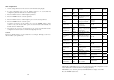
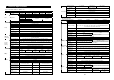
RS-232 Standard Interface port
The RS-232 interface uses a 9-pin female D-sub connector. This information consists of
data about utility, load and the UPS. The interface port pins and their functions are
identified in the following table.
Pin # Signal name Direction (re UPS) Functions
2 TxD Output TxD Output
3 RxD Input RxD / Inverter Off Input
5 Common Common
6 CTS Output Ac Fail Output
8 DCD Output Low Battery Output
9 RI Output +12 VDC Power
Fig.4
Caution! Max rated values 12Vdc/50mA