
Specifications
Applications Manual
12
1-800-927-9474
22-2
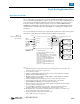
250W, 500W, and 750W Front Ends (cont)
Thermal Considerations
Free Convection Derating
• 250W: Derate output power linearly at 7.2W/˚C over 50˚C.
• 500W: Derate output power linearly at 14.3W/˚C over 50˚C.
• 750W: Derate output power linearly at 18.8W/˚C over 45˚C.
Forced Convection
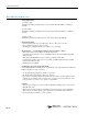
The curves below represent worst case data for chassis mounted (enclosed) front ends; i.e., low
line, full load. System conditions such as higher line voltage, lighter load or PC mount versions
of the front ends will increase reliability if the following data is used as the nominal design criteria.
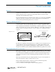
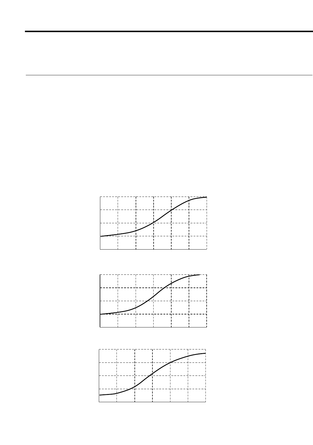
The sigmoid shape of the curves at low air flow is due to the chassis mount cover restricting the
airflow to the inboard components. When an airflow of approximately 200 LFM is achieved, the
velocity of air rushing over the cover causes air to be pulled in through the side perforations,
resulting in a rapid improvement in the cooling of internal components.
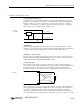
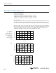
Figure 2.
Max. Ambient
Temperature vs.
Airflow (LFM) Over
Cover (Full Load,
90Vac Input,
Chassis Mount)
250W
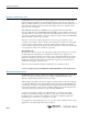
500W
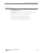
750W
40
80
70
60
50
500400300200100
0
Airflow (LFM)
Ambient Temperature °C
600
40
80
70
60
50
500400300200100
0
Airflow (LFM)
Ambient Temperature °C
600
40
80
70
60
50
600500400300200100
0
Airflow (LFM)
Ambient Temperature °C