
Manual

Emergi-Lite Tel: (888) 552-6467 Fax: (800) 316-4515 www.emergi-lite.com
05/11 750.1489 Rev. A
New Preceptor Series Die Cast LED Exit Sign
1/2
New Preceptor Series Die Cast LED Exit Sign
AC, AC/DC or Self-Powered
IMPORTANT SAFEGUARDS
When using electrical equipment, basic safety precautions should always
be taken including the following:
READ AND FOLLOW ALL SAFETY
INSTRUCTIONS
1. Do not use outdoors.
2. Do not let power supply cords touch hot surfaces.
3. Do not mount near gas or electric heaters.
4. Equipment should be mounted in locations and at heights where it will not
readily be subjected to tampering by unauthorized personnel.
5. The use of accessory equipment not recommended by the manufacturer
may cause an unsafe condition.
6. Do not use this equipment for other than intended use.
7. All servicing should be performed by qualified service personnel.
SAVE THESE INSTRUCTIONS
Installation Instructions
1. Turn off AC power.
2. Route AC unswitched circuit of rated voltage into electrical box and
leave 6” of wire length.
3. Remove the exit door by inserting a coin or a screwdriver in a notch at
the top or bottom of the door.
Note: back plate is screwed to the housing.
4. Remove plastic frame with everything attached on the plastic housing.
5. Determine the mounting position (end, wall or ceiling).
Note: canopy is required for end or ceiling mount.
6. Our system can accept input voltages of 120 VAC or 277 VAC.
Therefore, connect the Black (120 VAC) or Orange (277 VAC) and
White (common) leads to the building utility.
Connect the green wire to the ground.
Note: for dual curcuit option, there will be two sets of wires.
Unused primary wire must be insulated to prevent shorting.
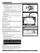
Wall mounting
a. No canopy required.
b. With the help of a flat head screwdriver, knock out the proper hole
pattern, including the center hole, in the back cover to mount to a
standard junction box (See Fig. 2).
c. Feed the AC supply leads out through the center hole and make the
proper connections (See step 5 and Fig.5).
d. Feed the excess wire into the junction box and secure the back
cover to the junction box using the junction box screws.
Figure 1
Figure 2
Figure 3
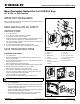
Part List
1. Back plate
2. Frame
3. Diffuser panel
4. Exit door
5. Hole plugs for Canopy
6. Canopy
7. Junction box screws (not
provided)
8. Cross-bar
9. Junction box
10. Canopy housing screw
11. Canopy cross-bar screw
12. Plastic housing
13. Back plate screws