
Install Instructions

www.emersonflowcontrols.com
ACP Automatic Expansion Valve
ACP Automatic Expansion Valve
Instruction Sheet
PA-00200
June 2007
11911 Adie Road P.O. Box 411400 St. Louis MO 63141 USA CUSTOMER SERVICE (314) 569-4666
GENERAL INFORMATION
The ACP Valve is an automatic expansion valve devel-
oped for small cooling units where the load is reasonably
constant, such as room air conditioners, domestic
refrigerators, drink dispensers, food dispensers, ice cream
cabinets bottle coolers, home freezers, ice cube makers,
ice cream freezers and milk coolers.
• Designed for use with: R-12, R-22, R-134a, R-401A,
R-402A, R-404A, R-407A,
R-407B, R-502 and R-507
• Maximum Working Pressure: 500 psig
• Maximum Working Temp.: 300°F
• UL file number: SA5312
• CSA file number: LR44005
SAFETY INSTRUCTIONS
1. WARNING: Read Installation and Safety instructions
thoroughly. Failure to follow instructions may result in
valve failure, system damage, and/or personal injury.
2. Do not use on service conditions or fluids not specifi-
cally cataloged without prior approval in writing of the
Emerson Climate Technologies Flow Controls Division
Applications Engineering Department.
3. Foreign matter in the ACP valve may cause diaphragm
failure, flooding, or starving. To insure that the system
is thoroughly clean and dry, we recommend the use of
an Emerson EK liquid line filter-drier.
4. Proper valve sizing is important. An oversized valve
may result in erratic control. An undersized valve may
considerably reduce system capacity.
5. Do not exceed Maximum Working Pressure
(450 PSIG).
6. Do not exceed Maximum Temperature Limits (300°F).
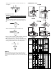
INSTALLATION
1. WARNING: Before opening any system, make sure
the pressure in the system is brought to and remains
at atmospheric pressure. Failure to comply may result
in system damage and/or personal injury.
= 0 psig
2. Valves may be installed in any position, but should be
located as close as possible to the distributor or
evaporator inlet. Refer to page 2 for valve dimensions.
3. Remove the necessary seal cap from the valve
entrances.
4. Be sure valve is installed so that it's flow design
corresponds to the flow direction through the piping.
Failure to comply will result in valve malfunction.
In
Out
5a.For SAE ACP Valves
1a) Install SAE line connections to valve.
Note: Look in the valve body for reference.