Installation Manual Par t Number 3-9000-760Revision E March 2015 DanielTM 3814 Liquid Ultrasonic Flow Meter
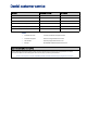
Daniel customer service Location Telephone number Fax number North America/Latin America +1.713.467.6000 +1.713.827.4805 Daniel Customer Service +1.713.827.6314 +1.713.827.6312 USA (toll free) +1.888.356.9001 +1.713.827.3380 Asia Pacific (Republic of Singapore) +65.6777.8211 +65.6777.0947.0743 Europe (Stirling Scotland, UK) +44 (0)1786.433400 +44 (0)1786.433401 Middle East Africa (Dubai, UAE) +971 4 8118100 +971 4 8865465 Email • Customer Service: tech.service@emersonprocess.
Signal words and symbols Pay special attention to the following signal words, safety alert symbols and statements: Safety alert symbol This is a safety alert symbol. It is used to alert you to potential physical injury hazards. Obey all safety messages that follow this symbol to avoid possible injury or death. Danger indicates a hazardous situation which, if not avoided, will result in death or serious injury.
Important safety instructions Daniel Measurement and Control, Inc. (Daniel) designs, manufactures and tests products to function within specific conditions. Because these products are sophisticated technical instruments, it is important that the owner and operation personnel strictly adhere both to the information printed on the product and to all instructions provided in this manual prior to installation, operation, and maintenance.
Product Operation Personnel: • To prevent personal injury, personnel must follow all instructions of this manual prior to and during operation of the product. • Follow all warnings, cautions, and notices marked on, and supplied with, this product. • Verify that this is the correct instruction manual for your Daniel product. If this is not the correct documentation, contact Daniel at 1-713-827-6314. You may also download the correct manual from: http://www.daniel.
Notice THE CONTENTS OF THIS PUBLICATION ARE PRESENTED FOR INFORMATIONAL PURPOSES ONLY, AND WHILE EVERY EFFORT HAS BEEN MADE TO ENSURE THEIR ACCURACY, THEY ARE NOT TO BE CONSTRUED AS WARRANTIES OR GUARANTEES, EXPRESSED OR IMPLIED, REGARDING THE PRODUCTS OR SERVICES DESCRIBED HEREIN OR THEIR USE OR APPLICABILITY. ALL SALES ARE GOVERNED BY DANIEL'S TERMS AND CONDITIONS, WHICH ARE AVAILABLE UPON REQUEST. WE RESERVE THE RIGHT TO MODIFY OR IMPROVE THE DESIGNS OR SPECIFICATIONS OF SUCH PRODUCTS AT ANY TIME.
Warranty and Limitations 1. LIMITED WARRANTY: Subject to the limitations contained in Section 2 herein, Daniel Measurement & Control, Inc.
Daniel 3814 Liquid Ultrasonic Meter Installation Manual 3-9000-760 Rev E Table of Contents March 2015 Contents Preface Daniel customer service Signal words and symbols Important safety instructions Notice Warranty and Limitations Section 1: Introduction 1.1 Typical Applications .................................................................................... 2 1.2 Features and benefits: ................................................................................. 3 1.
Table of Contents Daniel 3814 Liquid Ultrasonic Meter Installation Manual March 2015 3-9000-760 Rev E Section 3: Electrical installation 3.1 Cable length TTL mode .............................................................................. 39 3.2 Cable length Open Collector mode ............................................................. 39 3.3 Grounding meter electronics ...................................................................... 40 3.4 Conduit seals .....................................
Daniel 3814 Liquid Ultrasonic Meter Installation Manual 3-9000-760 Rev E List of Tables March 2015 List of Tables Table 1-1 Acronyms, abbreviations and definitions........................................................................ 4 Table 1-2 Meter specifications ..................................................................................................... 10 Table 2-1 Piping recommendation for uni-directional or bi-directional flow.................................
List of Tables March 2015 iv Daniel 3814 Liquid Ultrasonic Meter Installation Manual 3-9000-760 Rev E List of Tables
Daniel 3814 Liquid Ultrasonic Meter Installation Manual 3-9000-760 Rev E List of Figures March 2015 List of Figures Figure 1-1 Daniel MeterLink download and registration ................................................................ 6 Figure 1-2 Daniel 3814 Liquid Ultrasonic Flow Meter Design.......................................................... 8 Figure 1-3 Transmitter electronics enclosure with optional local display and glass endcap ...........
List of Figures March 2015 vi Daniel 3814 Liquid Ultrasonic Meter Installation Manual 3-9000-760 Rev E Figure 4-8 AMS Device Manager - Configure Manual Setup .......................................................... 74 Figure 4-9 Gating configuration parameter Edge gated, active high ............................................ 76 Figure 4-10 Gating configuration parameter Edge gated, active low..............................................
Daniel 3814 Liquid Ultrasonic Meter Installation Manual 3-9000-760 Rev E Section 1: Introduction March 2015 Section 1: Introduction Daniel 3814 Liquid Ultrasonic Meters have various configurations that meet a broad range of customer requirements. Each meter comes fully assembled from DanielTM Measurement and Control, Inc. and all parts and assemblies are tested prior to shipment.
Section 1: Introduction Daniel 3814 Liquid Ultrasonic Meter Installation Manual March 2015 1.
Daniel 3814 Liquid Ultrasonic Meter Installation Manual Section 1: Introduction 3-9000-760 Rev E 1.
Section 1: Introduction Daniel 3814 Liquid Ultrasonic Meter Installation Manual March 2015 1.
Daniel 3814 Liquid Ultrasonic Meter Installation Manual Section 1: Introduction 3-9000-760 Rev E March 2015 Table 1-1 Acronyms, abbreviations and definitions Acronym or abbreviation Definition m /h cubic meters per hour (volumetric flow rate) m3/s cubic meters per second (volumetric flow rate) mA milliamp (current unit) MAC Address Media Access Control (Ethernet Hardware Address -EHA) microinch (μinch) microinch (10-6 in) micron micrometer (10-6 m) MMU Memory Management Unit MPa megapas
Section 1: Introduction Daniel 3814 Liquid Ultrasonic Meter Installation Manual March 2015 1.4 3-9000-760 Rev E Daniel MeterLink software Daniel MeterLinkTM software has robust features for setting communications parameters, configuring your meter, collecting logs and reports, monitoring the meter health and alarm statuses. Daniel MeterLink may be downloaded at no charge from: http://www.daniel.com/um2.
Daniel 3814 Liquid Ultrasonic Meter Installation Manual Section 1: Introduction 3-9000-760 Rev E March 2015 Procedure 1. From the right panel under Quick Links, click the MeterLink Registration and Download link. 2. Click the Order Now button to complete the Online registration form. 3. Click Next to go to the order confirmation page. 4. Click Complete Order. You will receive a conformation e-mail with a hyperlink directing you to the download site. Click the link provided. 5. Click Save.
Section 1: Introduction Daniel 3814 Liquid Ultrasonic Meter Installation Manual March 2015 1.5 3-9000-760 Rev E 3814 liquid ultrasonic meter design The Daniel 3814 Liquid Ultrasonic Flow Meter is a four-path (eight transducers) in-line meter designed to measure the difference in signal transit time with and against the flow across one or more measurement path(s). A signal transmitted in the flow direction travels faster than one transmitted against the flow direction.
Daniel 3814 Liquid Ultrasonic Meter Installation Manual Section 1: Introduction 3-9000-760 Rev E March 2015 Figure 1-3 Transmitter electronics enclosure with optional local display and glass endcap The Daniel 3814 Liquid Ultrasonic Flow Meter is a four-path (eight transducers) in-line meter designed to measure the difference in signal transit time with and against the flow across one or more measurement path(s).
Section 1: Introduction Daniel 3814 Liquid Ultrasonic Meter Installation Manual March 2015 1.6 3-9000-760 Rev E Meter specifications FLUID CONTENTS MAY BE HAZARDOUS The meter must be fully depressurized and drained before attempting to remove the transducer housing. If fluid begins to leak from the transducer housing, immediately reinstall it. Failure to do so may cause serious injury or equipment damage.
Daniel 3814 Liquid Ultrasonic Meter Installation Manual 3-9000-760 Rev E Section 1: Introduction March 2015 Table 1-2 Meter specifications Body and Flange Pressure rating range U.S.
Section 1: Introduction Daniel 3814 Liquid Ultrasonic Meter Installation Manual March 2015 3-9000-760 Rev E Table 1-2 Meter specifications Electronic specifications Power Temperature flameproof Transmitter Electronic Enclosure and Base Electronics Enclosure Transducers Meter 10.4 VDC to 36 VDC 11 W typical power consumption Serial cable • Belden #9940 or equivalent (22 gauge) – Capacitance (pF/m) 121.397 (conductor to conductor) – Capacitance (pF/m) 219.
Daniel 3814 Liquid Ultrasonic Meter Installation Manual Section 1: Introduction 3-9000-760 Rev E March 2015 Table 1-2 Meter specifications Digital, analog, and frequency outputs Frequency/Digital Output(s) The meter has user-configurable selections for either a Frequency Output or Digital status (FODO) (Also see Section 3.6.
Section 1: Introduction Daniel 3814 Liquid Ultrasonic Meter Installation Manual March 2015 1.7 1.8 3-9000-760 Rev E Pre-installation considerations • Pipeline equipment code compliance, ANSI, ASME, etc. • Proper Inlet/outlet meter tube piping for reasonable stable flow to the settling chamber (first meter tube spool upstream of the meter). • Electrical safety compliance; UL,ULC, ATEX, IECEx etc.
Daniel 3814 Liquid Ultrasonic Meter Installation Manual Section 1: Introduction 3-9000-760 Rev E March 2015 Daniel 3810 Series Liquid Ultrasonic Meters are INMETRO certified. Refer to the 3810 Series Liquid Ultrasonic Flow Meter Tag, INMETRO Certification drawing DMC - 006173. Certificate number: NCC 11.0163 X Marking: --Ex d ia IIB T4 Gb IP66 W Electrical parameters: Refer to Section 1.
Section 1: Introduction Daniel 3814 Liquid Ultrasonic Meter Installation Manual March 2015 1.9 3-9000-760 Rev E Daniel 3810 Series certifications and approvals Daniel 3810 Series Liquid Ultrasonic Flow Meters have electrical, metrology, intrinsic safety and Pressure Equipment Directive certifications and approvals by the agencies listed below. Refer to the nameplate tag on the meter body, the wiring diagram (P/N DMC - 004936) in Appendix A and observe all safety precautions.
Daniel 3814 Liquid Ultrasonic Meter Installation Manual Section 1: Introduction 3-9000-760 Rev E March 2015 Approval Agencies • UL • ULC • DEMKO • INMETRO • NEPSI • GOSTR IMPORTANT Please consult Daniel Customer Service for the complete metrology approvals list. 1.10 FCC compliance This equipment has been tested and found to comply with the limits for a Class A digital device, pursuant to Part 15 of the FCC Rules.
Section 1: Introduction Daniel 3814 Liquid Ultrasonic Meter Installation Manual March 2015 1.11 3-9000-760 Rev E References [1] Gould Modbus Protocol Reference Guide, Rev. B, PI-MBUS-300 [2] API MPMS Chapter 5.8, Section 8-Measurement of Liquid Hydrocarbons by Ultrasonic Flow Meters Using Transit Time Technology, Edition: 2nd American Petroleum Institute / 01-Nov2011 [3] API MPMS Chapter 4.2, Displacement Provers, 3rd Edition | September 2003 | Reaffirmed: March 2011 [4] API MPMS Chapter 12.
Daniel 3814 Liquid Ultrasonic Meter Installation Manual Section 2: Mechanical installation 3-9000-760 Rev E March 2015 Section 2: Mechanical installation 2.1 Meter piping, lifting and mounting Refer to the following sections for piping recommendations, lifting with hoist rings and slings, mounting in heated or cooled pipelines and safety warnings and precautions. SURFACE TEMPERATURE HAZARD The meter body and piping may be extremely hot or cold.
Section 2: Mechanical installation Daniel 3814 Liquid Ultrasonic Meter Installation Manual March 2015 3-9000-760 Rev E CRUSHING HAZARD Do not remove flange stabilizers. Attempting to do so may allow the meter to roll, resulting in serious injury or equipment damage. A. A. Flange stabilizers ESCAPING FLUIDS HAZARD The purchaser of the meter is responsible for the selection of Daniel components/seals and materials compatible with the chemical properties of the measurement fluid.
Daniel 3814 Liquid Ultrasonic Meter Installation Manual Section 2: Mechanical installation 3-9000-760 Rev E March 2015 2.2 Meter components Daniel 3810 Series Ultrasonic Flow Meters are assembled, configured, and tested at the factory. The meter components include the Transmitter Electronics Enclosure, the Base Electronics. Enclosure and the Meter Body with transducer assemblies.
Section 2: Mechanical installation Daniel 3814 Liquid Ultrasonic Meter Installation Manual March 2015 3-9000-760 Rev E EXPLOSION OR FIRE HAZARD Conduit runs must have a sealing fitting within 50 mm (2 inches) of the enclosure to reduce the risk of an explosion or a fire. • During operation, keep covers tight. • During equipment maintenance, disconnect power before opening transmitter or base electronics. Clean cover joints before replacing. • DO NOT substitute meter components.
Daniel 3814 Liquid Ultrasonic Meter Installation Manual 3-9000-760 Rev E Section 2: Mechanical installation March 2015 Figure 2-2 Transmitter electronics enclosure with optional local display and glass endcap A. B. A. Transmitter electronics enclosure with glass endcap B.
Section 2: Mechanical installation Daniel 3814 Liquid Ultrasonic Meter Installation Manual March 2015 2.2.1 3-9000-760 Rev E Piping recommendations BURST HAZARD Before pipeline cleaning and maintenance (“pigging operations”), remove straightening vanes or flow conditioners. Failure to do so may cause excessive pressure in the meter system, resulting in serious injury/ death or equipment damage.
Daniel 3814 Liquid Ultrasonic Meter Installation Manual Section 2: Mechanical installation 3-9000-760 Rev E March 2015 Flow conditioning is recommended for best measurement results • Honed or un-honed meter tube(s) • Flow direction (unidirectional or bidirectional) • Correct meter size selection - too low may cause poor flow stability (thermal convection or too fast may cause erosion problems and resonance, cracks or failure of probes or thermowells (approximately 0.6 to 12 m/sec or 2 to 40 ft.
Section 2: Mechanical installation Daniel 3814 Liquid Ultrasonic Meter Installation Manual March 2015 3-9000-760 Rev E Figure 2-3 Piping recommendations unidirectional flow Figure 2-4 Piping recommendations bidirectional flow All pipe lengths are minimum: 26 • D = Nominal pipe size in inches (i.e.
Daniel 3814 Liquid Ultrasonic Meter Installation Manual Section 2: Mechanical installation 3-9000-760 Rev E March 2015 Refer to the ultrasonic meter product data sheet for piping information. The Liquid Ultrasonic Flow Meter Datasheet may be downloaded from the Daniel website: http://www2.emersonprocess.com/en-US/brands/daniel/Flow/ultrasonics/Pages/Ultrasonic-Series3800.
Section 2: Mechanical installation Daniel 3814 Liquid Ultrasonic Meter Installation Manual March 2015 2.2.2 3-9000-760 Rev E High Viscosity piping requirements The piping requirements for High Viscosity meter applications are shown in Figure 2-5.
Daniel 3814 Liquid Ultrasonic Meter Installation Manual Section 2: Mechanical installation 3-9000-760 Rev E 2.3 March 2015 Meter safety for hoist rings and lifting slings A Daniel Liquid Ultrasonic Flow Meter can be safely lifted and maneuvered into and out of a meter run for installation or service by obeying the following instructions.
Section 2: Mechanical installation Daniel 3814 Liquid Ultrasonic Meter Installation Manual March 2015 3-9000-760 Rev E When lifting a Daniel Ultrasonic Meter by itself, Daniel recommends two methods. These methods are: • Using appropriately rated Safety Engineered Swivel Hoist Rings installed in the Daniel Ultrasonic Meter end flanges. • Using appropriately rated lifting slings positioned at designated areas of the Daniel Ultrasonic Meter.
Daniel 3814 Liquid Ultrasonic Meter Installation Manual Section 2: Mechanical installation 3-9000-760 Rev E March 2015 Figure 2-7 Safety approved hoist ring and non-compliant eye bolt Safety engineered swivel hoist ring Eye bolt Safety precautions using safety engineered swivel hoist rings Read and follow the Safety Precautions listed below: 1. Meters must only be lifted by personnel properly trained in the safe practices of rigging and lifting. 2.
Section 2: Mechanical installation Daniel 3814 Liquid Ultrasonic Meter Installation Manual March 2015 3-9000-760 Rev E 8. Always use separate slings to each hoist ring. NEVER reeve one sling through both hoist rings. The slings must be of equal length. Each sling must have a load rating that equals or exceeds the hoist ring load rating. The angle between the two slings going to the hoist rings must never exceed 90 degrees or the load rating of the hoist rings will be exceeded.
Daniel 3814 Liquid Ultrasonic Meter Installation Manual 3-9000-760 Rev E Section 2: Mechanical installation March 2015 9. NEVER allow the slings to contact the electronics enclosure. Damage to the enclosure may occur. Use a spreader bar with the slings to prevent contact with the electronics enclosure and the base enclosure (see Figure 2-10).
Section 2: Mechanical installation Daniel 3814 Liquid Ultrasonic Meter Installation Manual March 2015 3-9000-760 Rev E prior to be placed in any further service. If a proper inspection cannot be performed, discard the hoist ring. 11. NEVER lift with any device, such as hooks, chains, or cables that could create side pulls that could damage the ring of the hoist ring. 12. NEVER lift more than the ultrasonic meter assembly including electronics and transducers with the hoist rings.
Daniel 3814 Liquid Ultrasonic Meter Installation Manual Section 2: Mechanical installation 3-9000-760 Rev E March 2015 What size safety engineered swivel hoist ring do you need? To determine the size of the hoist rings required for your meter, use the appropriate table below for Liquid Ultrasonic Meters (see Table 2-2). Look down the column that matches the ANSI rating of your meter. Find the row that contains your meter size. Follow the row to the end to find the appropriate hoist ring part number.
Section 2: Mechanical installation Daniel 3814 Liquid Ultrasonic Meter Installation Manual March 2015 2.3.2 3-9000-760 Rev E Appropriately rated lifting slings The following instructions are intended to provide general guidelines for proper lifting slings of the Daniel 3814 Ultrasonic meter by itself. These instructions are intended to be followed in addition to your company's standards or the DOE-STD-1090-2004 Hoisting and Rigging standard if such company standards do not exist.
Daniel 3814 Liquid Ultrasonic Meter Installation Manual 3-9000-760 Rev E Section 2: Mechanical installation March 2015 6. NEVER allow the slings to contact the electronics enclosure or the transducer cabling. Damage to the meter may occur.
Section 2: Mechanical installation Daniel 3814 Liquid Ultrasonic Meter Installation Manual March 2015 2.4 3-9000-760 Rev E Mounting requirements in heated or cooled pipelines The ambient operating temperature of the Daniel 3814 Liquid Ultrasonic Flow Meter electronics (i.e. Flameproof enclosure and Intrinsically safe base enclosure) is -40 oC (-40 oF) to +60 oC (+140 oF).
Daniel 3814 Liquid Ultrasonic Meter Installation Manual Section 3: Electrical installation 3-9000-760 Rev E March 2015 Section 3: Electrical installation 3.1 Cable length TTL mode The maximum cable length is 2000 feet when the “TTL” mode is selected. 3.2 Cable length Open Collector mode For the “open collector” mode, the maximum cable length depends on the cable parameters, pull-up resistance used, the maximum frequency to output, and frequency input parameters being driven.
Section 3: Electrical installation Daniel 3814 Liquid Ultrasonic Meter Installation Manual March 2015 3.3 3-9000-760 Rev E Grounding meter electronics Daniel Liquid Ultrasonic Flow Meter electronics should be internally grounded for intrinsically safe operations. Connect a wire to the chassis ground lug installed inside the Transmitter Electronics Enclosure as the primary ground. Secondary grounds are located outside of the Transmitter Electronics Enclosure (see Figure 3-2).
Daniel 3814 Liquid Ultrasonic Meter Installation Manual Section 3: Electrical installation 3-9000-760 Rev E March 2015 Figure 3-2 External ground lug A. A. External ground lug 3.4 Conduit seals Daniel 3814 Liquid Ultrasonic Meters require conduit seals for installations in hazardous environments. Adhere to safety instructions to protect personnel and equipment. HAZARDOUS VOLTAGE Do not open the Transmitter Electronics Enclosure in a flammable gas area. Disconnect power before servicing.
Section 3: Electrical installation Daniel 3814 Liquid Ultrasonic Meter Installation Manual March 2015 3.4.1 3-9000-760 Rev E Startup for systems using explosion-proof conduit 1. Assemble conduit to the Transmitter Electronics Enclosure. A conduit seal is required within 18 inches (457 mm) of the enclosure. 2. Check to make certain that all power to field wiring is turned OFF. HAZARDOUS VOLTAGE INSIDE Do not open in flammable gas area. Disconnect all power to the meter.
Daniel 3814 Liquid Ultrasonic Meter Installation Manual Section 3: Electrical installation 3-9000-760 Rev E 3.4.2 March 2015 Startup for systems that use flame-proof cable HAZARDOUS VOLTAGE INSIDE Do not open the Transmitter Electronics Enclosure when an explosive gas atmosphere is present. Disconnect equipment from supply circuit before opening the enclosure. Failure to follow the instructions in this manual may result in serious injury or death. 1.
Section 3: Electrical installation March 2015 3.5 Daniel 3814 Liquid Ultrasonic Meter Installation Manual 3-9000-760 Rev E Wiring and I/O Daniel MeterLink uses the TCP/IP protocol to communicate with the 960-24™ MSTS electronics instead of Modbus ASCII or RTU. The TCP/IP protocol only works across either Ethernet, RS-485 full duplex (i.e., 4-wire), or RS-232. Daniel MeterLinkTMcan communicate with multiple meters if they are multi-dropped using 4-wire full duplex RS-485 mode.
Daniel 3814 Liquid Ultrasonic Meter Installation Manual Section 3: Electrical installation 3-9000-760 Rev E 3.5.1 March 2015 CPU Module labeling and LED indicators The meter’s metrology mode and the status of the data transfer from the Acquisition Module to the CPU Module is indicated via light-emitting diode (LED) status indicators. The Write PROT. with protects the meter’s configuration, Figure 3-3 CPU Module labeling and LED indicators G. F. C. D. E. B. A. A. Acquisition/Measurement mode B.
Section 3: Electrical installation Daniel 3814 Liquid Ultrasonic Meter Installation Manual March 2015 3-9000-760 Rev E Table 3-2 CPU Module labeling and LED functions CPU Module switch Function WRITE PROT. • • DHCP • • • PORT A • • • • MEAS Write-protect mode - with switch in the ON position (default setting) protects configuration and firmware overwrites.
Daniel 3814 Liquid Ultrasonic Meter Installation Manual Section 3: Electrical installation 3-9000-760 Rev E March 2015 Ethernet communications The Ethernet port IP address, subnet mask, and gateway address are software-configurable. In addition, a meter can be configured to act as a DHCP (Dynamic Host Configuration Protocol) server to assign an IP address to a PC or laptop running Daniel MeterLink. The DHCP server facility is not intended to act as a general purpose DHCP server for a wider network.
Section 3: Electrical installation Daniel 3814 Liquid Ultrasonic Meter Installation Manual March 2015 3-9000-760 Rev E A DIN 41612 48-pin connector is the interface from the CPU Module to the Field Connection Board (male end located on the back of the Field Connection Board). Serial connections Use serial cable (Daniel P/N 3-2500-401) to connect to a PC running Daniel MeterLinkTM.
Daniel 3814 Liquid Ultrasonic Meter Installation Manual Section 3: Electrical installation 3-9000-760 Rev E March 2015 If not using Ethernet, a full duplex serial connection is necessary for Daniel MeterLink to communicate with a Daniel 3814 Liquid Ultrasonic Flow Meter.
Section 3: Electrical installation Daniel 3814 Liquid Ultrasonic Meter Installation Manual March 2015 3.6 3-9000-760 Rev E I/O connections The 960-24™ MSTS provides I/O connections on the CPU Module. Figure 3-5 CPU Module I/O connections A. B. C. D. A. Frequency/Digital Output 2 B. Frequency/Digital Output 3 C. Analog Output 2 - 4-20mA output D.
Daniel 3814 Liquid Ultrasonic Meter Installation Manual Section 3: Electrical installation 3-9000-760 Rev E 3.6.1 March 2015 Frequency/Digital outputs The meter has three user-configurable selections for configuring either a Frequency output or Digital output (FODO).
Section 3: Electrical installation Daniel 3814 Liquid Ultrasonic Meter Installation Manual March 2015 3-9000-760 Rev E Frequency or Digital Outputs (FODO 3) source • FO1A, DO1A, FO1B, DO1B, FO2A, DO2A, FO2B, DO2B • FO1A, DO1A, FO1B, DO1B, FO2A, DO2A, FO2B, DO2B • Frequency output 1A is based on frequency content (Actual - Uncorrected Flow Rate) • Frequency output 1B is based on frequency content and Frequency 1B Phase • Frequency output 2A is based on frequency content (Actual - Uncorrected Flo
Daniel 3814 Liquid Ultrasonic Meter Installation Manual Section 3: Electrical installation 3-9000-760 Rev E March 2015 Table 3-5 Frequency/Digital Outputs possible configurations Frequency/Digital output Frequency /Digital Output 11 Frequency /Digital Output 22 or Frequency /Digital Output 32 Source configuration • • • • Frequency output 1A Frequency output 1B Digital output 1A Digital output 1B • • • • • • • • Frequency output 1A Frequency output 1B Digital output 1A Digital output 1B Frequency ou
Section 3: Electrical installation Daniel 3814 Liquid Ultrasonic Meter Installation Manual March 2015 3.6.2 3-9000-760 Rev E Analog input settings The 960-24™ MSTS has the capability to sample analog temperature (Analog Input 1) and pressure (Analog Input 2) with 4-20 mA signals. These analog input signals are configured to sink. The two independent analog input circuits are configured for conventional 4-20 mA service.
Daniel 3814 Liquid Ultrasonic Meter Installation Manual Section 3: Electrical installation 3-9000-760 Rev E 3.6.6 March 2015 Configuration protect switch settings The meter’s configuration parameters and firmware can be protected against changes via CPU Module Write PROT. switch as follows: Table 3-7 Configuration protect switch settings CPU Module switch Configuration protected Configuration unprotected WRITE PROT. ON OFF A complete list of write-protected parameters are in Appendix A. 3.6.
Section 3: Electrical installation Daniel 3814 Liquid Ultrasonic Meter Installation Manual March 2015 3.6.8 3-9000-760 Rev E Securing the meter Security seals protect the integrity of the meter metrology and prevent tampering with transducer assemblies. The following sections detail how to properly seal the Daniel 3814 Liquid Ultrasonic Flow Meter after commissioning. The security seal wires are commercially available. Be sure to set the WRITE PROT.
Daniel 3814 Liquid Ultrasonic Meter Installation Manual Section 3: Electrical installation 3-9000-760 Rev E March 2015 2. Install the security seal wire into and through one of the two holes in the end cap. Choose holes that minimize counterclockwise rotation of the end cap when the security wire is taut (maximum wire diameter.078 inch; 2.0mm). Figure 3-9 Transmitter Electronics Enclosure security seals A. B. A. Transmitter Electronics Enclosure end cap B.
Section 3: Electrical installation Daniel 3814 Liquid Ultrasonic Meter Installation Manual March 2015 3-9000-760 Rev E Base Enclosure Security Seals Use the following instructions to install the security seal wire on the Base Enclosure. 1. Install security wire seal into and through the hole in the socket head screw on the Base Enclosure cover (maximum wire diameter.078 inch; 2.0mm). Figure 3-10 Base Enclosure wire seal installation A. B. A. Base Enclosure cover B. Security wire seals 2.
Daniel 3814 Liquid Ultrasonic Meter Installation Manual 3-9000-760 Rev E Section 3: Electrical installation March 2015 3. Feed the security wire beneath the Transmitter Electronics Enclosure and through the adjacent socket head screw. Twist the wire, removing all slack and seal. Figure 3-11 Base Enclosure security seals A. B. C. D. A. Transmitter Electronics Enclosure B. Security wire seals e C. Transmitter Electronics endcap security latch D. Base Enclosure 4.
Section 3: Electrical installation Daniel 3814 Liquid Ultrasonic Meter Installation Manual March 2015 3-9000-760 Rev E Transducer assembly security seal Use the following instructions and Figure 3-12 to install the security seal wire on the transducer assembly. 1. For each Transducer Assembly, install a security seal wire into and through one of the two holes of the Locking Ring bolt (Item C) and through one of the two holes in the Transducer Retainer (Item D).
Daniel 3814 Liquid Ultrasonic Meter Installation Manual 3-9000-760 Rev E 3.6.9 Section 3: Electrical installation March 2015 Sealing the unit The unit should be properly sealed with a sealing compound after electrical connections have been tested according to the customer's Best Practices schedule. Some areas require a witnessed Acceptance Test for the installed system and require that the meter run for a predetermined length of time (approximately one to two weeks) before the unit is sealed.
Section 3: Electrical installation March 2015 62 Daniel 3814 Liquid Ultrasonic Meter Installation Manual 3-9000-760 Rev E Sealing the unit
Daniel 3814 Liquid Ultrasonic Meter Installation Manual 3-9000-760 Rev E Section 4: Configuration March 2015 Section 4: Configuration After the mechanical and electrical installation is complete and connectivity is established, use the Daniel MeterLinkTM Software for Gas and Liquid Ultrasonic Meters Quick Start Manual (P/N 3-9000-763) to setup software communications with the meter. 4.1 4.2 Daniel MeterLink Setup 1. Review the software operating system, hardware and peripheral requirements. 2.
Section 4: Configuration Daniel 3814 Liquid Ultrasonic Meter Installation Manual March 2015 3-9000-760 Rev E 4. Configure Frequency output 1 and Frequency output 2 content (Daniel Liquid Ultrasonic Meters content is Uncorrected flow rate), flow direction, Channel B phase, maximum frequency output (Hertz) and Full scale volumetric flow rate. Select Next to continue to Meter Digital Outputs. 5.
Daniel 3814 Liquid Ultrasonic Meter Installation Manual Section 4: Configuration 3-9000-760 Rev E March 2015 Display Items The valid labels, descriptions and units for the local display are shown below: Table 4-1 Local display labels, descriptions and valid units Local Display label and description QFLOW — Uncorrected volume flow rate • BBL – Barrels • GAL – Gallons • L – Liters • CM – Cubic Meters • MCM – Thousand Cubic Meters TDYVL — Current day’s forward uncorrected volume • +BBL – Barrels • +GAL –
Section 4: Configuration Daniel 3814 Liquid Ultrasonic Meter Installation Manual March 2015 3-9000-760 Rev E Table 4-1 Local display labels, descriptions and valid units Local Display label and description VEL — Average flow velocity • Ft/S – Feet per second • M/S – Meters per second SOS — Average sound velocity • Ft/S – Feet per second • M/S – Meters per second TEMP — Flow-condition temperature • DEGF – Degrees Fahrenheit • DEGC – Degrees Celsius PRESS — Flow-condition pressure • PSI – Pound per square
Daniel 3814 Liquid Ultrasonic Meter Installation Manual 3-9000-760 Rev E Section 4: Configuration March 2015 Display units The Meter volume units displayed are either U.S. Customary or Metric. To modify the Display Units, configure the Meter units system in the Field Setup Wizard — General Page. • • U.S.
Section 4: Configuration Daniel 3814 Liquid Ultrasonic Meter Installation Manual March 2015 4.3 3-9000-760 Rev E Using AMS Device Manager to configure the meter This procedure assumes you have AMS Device Manager installed on the host computer and have downloaded the latest Daniel Liquid Ultrasonic Meter Device Description (DD). If not installed, click the link below to download the AMS device installation tool kit. http://www2.emersonprocess.
Daniel 3814 Liquid Ultrasonic Meter Installation Manual 3-9000-760 Rev E Section 4: Configuration March 2015 10. Click the Daniel Industries Liquid 3810 Series Rev 1 hyperlink. The file download dialog displays. Click the Save button to save the files to your host system. You may use the default download location or change the directory. 11. AMS file download options 12. Click the Save button to complete the file download. Figure 4-2 AMS file download complete 13.
Section 4: Configuration Daniel 3814 Liquid Ultrasonic Meter Installation Manual March 2015 3-9000-760 Rev E 17. Click the Configure tab, and then select Guided Setup, Manual Setup or Alert Setup.
Daniel 3814 Liquid Ultrasonic Meter Installation Manual 3-9000-760 Rev E Section 4: Configuration March 2015 AMS Device Manager - Guided Setup The Guided setup wizard provides configuration parameter settings for the meter. The Guided Setup is a subset of the Manual Setup parameters. Figure 4-5 AMS Device Manager - Guided Setup Note: Before writing configuration changes to your meter, make sure you have saved the Configuration file and Maintenance log. Procedure 1.
Section 4: Configuration Daniel 3814 Liquid Ultrasonic Meter Installation Manual March 2015 3-9000-760 Rev E 4. After all of the data shown below is entered, click Apply to write the parameters to the meter. a. b. c. 5. Click Setup HART to configure the HART parameters (tag, date, descriptor, message text, Final Assembly number, Poll address and number of response preambles are displayed). After all of the data is entered click Apply to write the parameters to the meter. 6.
Daniel 3814 Liquid Ultrasonic Meter Installation Manual Section 4: Configuration 3-9000-760 Rev E March 2015 d. Click the All Variables tab to view a graphical display of the Primary, Secondary, Third and Fourth Variables. Figure 4-6 AMS Device Manager - Service Tools All Variables status indicators 8. Click OK to return to the Overview page. 9. Enable the Write Protect switch on the CPU Module to protect the meter’s configuration. 10. From the Overview window, click Display Meter K-Factors.
Section 4: Configuration Daniel 3814 Liquid Ultrasonic Meter Installation Manual March 2015 3-9000-760 Rev E AMS Device Manager - Manual Setup Use the Manual Setup wizard to configure the meter’s parameters. See Figure 4-3 and Figure 4-4 and from the AMS Device Manager Configure menu click Manual Setup. Figure 4-8 AMS Device Manager - Configure Manual Setup Procedure 74 1. If installed, remove security wires from the endcap and the Bracket/Cover hex head bolts that secures the Base Enclosure. 1.
Daniel 3814 Liquid Ultrasonic Meter Installation Manual Section 4: Configuration 3-9000-760 Rev E March 2015 6. Click the Frequency/Digital Outputs tab. Follow the configuration instructions in the AMS Device Manager - Guided Setup, Step 3 a.). (Refresh Note: If changes are made to any Source variable on this page, apply the changes and navigate to the Guided Setup page. Navigate back to the Manual Setup for the changes to be reflected in other Manual Setup pages).
Section 4: Configuration Daniel 3814 Liquid Ultrasonic Meter Installation Manual March 2015 3-9000-760 Rev E b.
Daniel 3814 Liquid Ultrasonic Meter Installation Manual 3-9000-760 Rev E Section 4: Configuration March 2015 12. Click the Alert Setup tab (from the main Configuration page). Figure 4-13 Configure Flow Analysis Alert 13. Click the Flow Analysis tab to select Configure Reverse Flow Detection, if desired. The default setting is Disabled. Click the Disabled button to send the feature command to the meter. Check for a response error. If no error response is received, click the Enable button. a. b. c.
Section 4: Configuration Daniel 3814 Liquid Ultrasonic Meter Installation Manual March 2015 3-9000-760 Rev E 14. Click the Service Tools tab to access the device alerts, variables, trends and maintenance statuses or to edit the configuration parameters. a. Click the Service Tools|Alerts tab. If an alert condition exists, the alert type and description displays. Recommended actions are listed to assist you in a resolution.
Daniel 3814 Liquid Ultrasonic Meter Installation Manual 3-9000-760 Rev E Section 4: Configuration March 2015 c. Click the Service Tools|Variables tab. The Variables page displays tabs for the device’s Flow Data, Path Information, Flow Totals, and All Variables). Figure 4-16 AMS Device Manager - Service Tools d. e. f. The Service Tools|Flow Data page includes charts for flow and sound velocities.
Section 4: Configuration Daniel 3814 Liquid Ultrasonic Meter Installation Manual March 2015 3-9000-760 Rev E g. Click Service Tools|Variables|All Variables tab to view Primary, Secondary, Third and Fourth Variable parameter status. Figure 4-17 AMS Device Manager - Service Tools All Variables Gauges display each variable’s status as good or bad. If a status is bad refer to the Service Tools Alerts page for recommended actions to resolve the alert condition.
Daniel 3814 Liquid Ultrasonic Meter Installation Manual 3-9000-760 Rev E Section 4: Configuration March 2015 h. Click the Service Tools|Trends tab to display the device variables (uncorrected volume flow rate, pressure and temperature) trends. Figure 4-18 AMS Device Manager - Service Tools Trends Primary and Secondary variables display real-time uncorrected volume flow rate trends. The third and fourth variables charts displays trends for temperature and pressure. 15.
Section 4: Configuration Daniel 3814 Liquid Ultrasonic Meter Installation Manual March 2015 4.4 3-9000-760 Rev E Using a Field Communicator to configure the meter important Follow all guidelines and precautions described in the Field Communicator User Manual and in the 3818 LNG Liquid Ultrasonic Flow Meter documentation when working in a hazardous area.
Daniel 3814 Liquid Ultrasonic Meter Installation Manual Section 4: Configuration 3-9000-760 Rev E March 2015 Procedure 1. Remove electrical power to the meter. If installed, remove the endcap security latches and seals and then, remove the endcap. 2. Refer to the Field Communicator Users Manual wiring diagrams and commissioning instructions provided with your handheld device. Register the product to activate the end user license. 3. Fully charge the Field Communicator battery prior to use.
Section 4: Configuration Daniel 3814 Liquid Ultrasonic Meter Installation Manual March 2015 3-9000-760 Rev E 5. Wire Analog Input 1 (AI1) and Analog Output 1 (AO1) as shown in Figure 4-20 and Appendix A, drawing DMC-005324. Figure 4-20 Field Communicator wiring diagram for the 3810 Series electronics 6. Use the leads provided with the Field Communicator to connect to your device. 7. Press and hold the Power button on the Field Communicator until the green light blinks. 8.
Daniel 3814 Liquid Ultrasonic Meter Installation Manual Section 4: Configuration 3-9000-760 Rev E 4.5 March 2015 Security seals for the meter (optional) For the integrity of the meter metrology and to prevent tampering with the transmitter electronics and transducer assemblies, attach security latches on the end caps and install security wires on the Transmitter Electronics Enclosure end caps, the Base Enclosure hex head bolts. See Section 3.6.8 and Section 3.6.9.
Section 4: Configuration March 2015 86 Daniel 3814 Liquid Ultrasonic Meter Installation Manual 3-9000-760 Rev E Security seals for the meter (optional)
Daniel 3814 Liquid Ultrasonic Meter Installation Manual Engineering drawings 3-9000-760 Rev E March 2015 Appendix A: Engineering drawings APPENDIX APAGE 498 A.
Engineering drawings March 2015 88 Daniel 3814 Liquid Ultrasonic Meter Installation Manual 3-9000-760 Rev E Daniel 3810 Series Liquid Ultrasonic Flow Meter drawings
Daniel 3814 Liquid Ultrasonic Meter Installation Manual Open source licenses 3-9000-760 Rev E March 2015 Appendix B: Open source licenses A Source code for executable files or libraries included in this product is provided per the indicated license in the table below. Hyperlinks to the controlling organization's websites are included in Section B.1 through Section B.4. Table B-1 Open source licences Package File specification License Summary base_libs-1.
Open source licenses Daniel 3814 Liquid Ultrasonic Meter Installation Manual March 2015 3-9000-760 Rev E Package File specification License Summary strace-4.5.14-1 strace BSD trace system calls associated with a running pro sysconfig-1.2-1 sysconfig GPL System configuration package sysfsutils-2.1.0-1 sysfsutils GPL/LGPL sysfs utilities tcpdump-3.8.3-1 tcpdump BSD A network traffic monitoring tool termcap-1.2-1 termcap BSD minimal /etc/termcap needed by minicom etc u-boot-1.3.
Daniel 3814 Liquid Ultrasonic Meter Installation Manual 3-9000-760 Rev E Open source licenses March 2015 The GNU General Public License (GPL) Version 2, June 1991 Copyright (C) 1989, 1991 Free Software Foundation, Inc. 59 Temple Place, Suite 330, Boston, MA 02111-1307 USA Everyone is permitted to copy and distribute verbatim copies of this license document, but changing it is not allowed. Preamble The licenses for most software are designed to take away your freedom to share and change it.
Open source licenses Daniel 3814 Liquid Ultrasonic Meter Installation Manual March 2015 3-9000-760 Rev E For example, if you distribute copies of such a program, whether gratis or for a fee, you must give the recipients all the rights that you have. You must make sure that they, too, receive or can get the source code. And you must show them these terms so they know their rights.
Daniel 3814 Liquid Ultrasonic Meter Installation Manual Open source licenses 3-9000-760 Rev E March 2015 TERMS AND CONDITIONS FOR COPYING, DISTRIBUTION AND MODIFICATION 0. This License applies to any program or other work which contains a notice placed by the copyright holder saying it may be distributed under the terms of this General Public License.
Open source licenses Daniel 3814 Liquid Ultrasonic Meter Installation Manual March 2015 3-9000-760 Rev E 2. You may modify your copy or copies of the Program or any portion of it, thus forming a work based on the Program, and copy and distribute such modifications or work under the terms of Section 1 above, provided that you also meet all of these conditions: a) You must cause the modified files to carry prominent notices stating that you changed the files and the date of any change.
Daniel 3814 Liquid Ultrasonic Meter Installation Manual 3-9000-760 Rev E Open source licenses March 2015 In addition, mere aggregation of another work not based on the Program with the Program (or with a work based on the Program) on a volume of a storage or distribution medium does not bring the other work under the scope of this License. 3.
Open source licenses March 2015 Daniel 3814 Liquid Ultrasonic Meter Installation Manual 3-9000-760 Rev E If distribution of executable or object code is made by offering access to copy from a designated place, then offering equivalent access to copy the source code from the same place counts as distribution of the source code, even though third parties are not compelled to copy the source along with the object code. 4.
Daniel 3814 Liquid Ultrasonic Meter Installation Manual 3-9000-760 Rev E Open source licenses March 2015 Program by all those who receive copies directly or indirectly through you, then the only way you could satisfy both it and this License would be to refrain entirely from distribution of the Program.
Open source licenses Daniel 3814 Liquid Ultrasonic Meter Installation Manual March 2015 3-9000-760 Rev E conditions either of that version or of any later version published by the Free Software Foundation. If the Program does not specify a version number of this License, you may choose any version ever published by the Free Software Foundation. 10.
Daniel 3814 Liquid Ultrasonic Meter Installation Manual Open source licenses 3-9000-760 Rev E March 2015 How to Apply These Terms to Your New Programs If you develop a new program, and you want it to be of the greatest possible use to the public, the best way to achieve this is to make it free software which everyone can redistribute and change under these terms. To do so, attach the following notices to the program.
Open source licenses Daniel 3814 Liquid Ultrasonic Meter Installation Manual March 2015 3-9000-760 Rev E The hypothetical commands `show w' and `show c' should show the appropriate parts of the General Public License. Of course, the commands you use may be called something other than `show w' and `show c'; they could even be mouse-clicks or menu items--whatever suits your program.
Daniel 3814 Liquid Ultrasonic Meter Installation Manual Open source licenses 3-9000-760 Rev E B.2 March 2015 GNU Lesser General Public License GNU LESSER GENERAL PUBLIC LICENSE Version 3, 29 June 2007 Copyright © 2007 Free Software Foundation, Inc. Everyone is permitted to copy and distribute verbatim copies of this license document, but changing it is not allowed.
Open source licenses Daniel 3814 Liquid Ultrasonic Meter Installation Manual March 2015 3-9000-760 Rev E The "Corresponding Application Code" for a Combined Work means the object code and/or source code for the Application, including any data and utility programs needed for reproducing the Combined Work from the Application, but excluding the System Libraries of the Combined Work. 1. Exception to Section 3 of the GNU GPL.
Daniel 3814 Liquid Ultrasonic Meter Installation Manual Open source licenses 3-9000-760 Rev E March 2015 4. Combined Works.
Open source licenses Daniel 3814 Liquid Ultrasonic Meter Installation Manual March 2015 3-9000-760 Rev E 5. Combined Libraries.
Daniel 3814 Liquid Ultrasonic Meter Installation Manual Open source licenses 3-9000-760 Rev E B.3 March 2015 BSD Open Source License For more details about the Open SourceTM BSD license or the Open Source Initiative, follow the link below: http://www.opensource.org/licenses/bsd-license.php Copyright (c) , All rights reserved.
Open source licenses Daniel 3814 Liquid Ultrasonic Meter Installation Manual March 2015 B.4 3-9000-760 Rev E M.I.T License For more details about the Open SourceTM MIT license or the Open Source Initiative follow the link below: http://www.opensource.org/licenses/mit-license.
Daniel 3814 Liquid Ultrasonic Meter Installation Manual Index 3-9000-760 Rev E March 2015 Appendix C: Index G C.1 H Manual index A Acronyms, abbreviations and definitions ......................... 4 American Drill Bushing Company ..................................... 34 AMS Device Manager - Manual Setup .............................. 74 AMS™ Suite Device Manager................................................ 4 Analog input switch settings .....................................................
Index Daniel 3814 Liquid Ultrasonic Meter Installation Manual March 2015 Meter specifications .............................................................. 10 Accuracy Limits ............................................................... 11 Analog Input(s) ............................................................... 12 Analog output(s) ............................................................ 13 Body and flange pressure rating range (psi) .......... 11 Communications .............................
P/N 3-9000-760 Rev E 2015 Daniel Measurement and Control, Inc. 11100 Brittmoore Park Drive Houston, TX 77041 USA T+1 713-467-6000 F+1 713-827-4805 USA Toll Free 1 888-356-9001 Daniel Measurement Services, Inc. T +1 713-827-6314 www.Daniel.com Europe: Stirling, Scotland, UK T + 44-1786-433400 Middle East: Africa: Dubai, UAE T +971-4-811-8100 Asia Pacific: Singapore T +65-677-8211 This product is a core component of the PlantWeb digital plant architecture. © 2015 Daniel Measurement and Control, Inc.