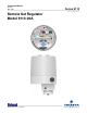
Instruction Manual CI-9110 Mar. 2007 Remote Set Regulator Model 9110-00A www.EmersonProcess.
IMPORTANT! READ INSTRUCTIONS BEFORE STARTING! Be sure that these instructions are carefully read and understood before any operation is attempted. Improper use of this device in some applications may result in damage or injury. The user is urged to keep this book filed in a convenient location for future reference. These instructions may not cover all details or variations in equipment or cover every possible situation to be met in connection with installation, operation or maintenance.
WARRANTY A. Bristol warrants that goods described herein and manufactured by Bristol are free from defects in material and workmanship for one year from the date of shipment unless otherwise agreed to by Bristol in writing. B. Bristol warrants that goods repaired by it pursuant to the warranty are free from defects in material and workmanship for a period to the end of the original warranty or ninety (90) days from the date of delivery of repaired goods, whichever is longer. C.
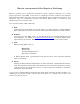
How to return material for Repair or Exchange Before a product can be returned to Bristol for repair, upgrade, exchange, or to verify proper operation, form (GBU 13.01) must be completed in order to obtain a RA (Return Authorization) number and thus ensure an optimal lead time. Completing the form is very important since the information permits the Bristol Repair Dept. to effectively and efficiently process the repair order. You can easily obtain a RA number by: A. FAX Completing the form (GBU 13.
Bristol Inc. Repair Authorization Form (off-line completion) (Providing this information will permit Bristol Inc. to effectively and efficiently process your return. Completion is required to receive optimal lead time. Lack of information may result in increased lead times.) Date___________________ RA #___________________SH_ Standard Repair Practice is as follows: Variations to this is practice may be requested in the “Special Requests” section.
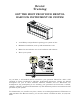
Bristol Training GET THE MOST FROM YOUR BRISTOL BABCOCK INSTRUMENT OR SYSTEM • Avoid Delays and problems in getting your system on-line • Minimize installation, start-up and maintenance costs. • Make the most effective use of our hardware and software. • Know your system. As you know, a well-trained staff is essential to your operation. Bristol Inc. offers a full schedule of classes conducted by full-time, professional instructors.
A Few Words About Bristol Inc. For over 100 years, Bristol® has been providing innovative solutions for the measurement and control industry. Our product lines range from simple analog chart recorders, to sophisticated digital remote process controllers and flow computers, all the way to turnkey SCADA systems. Over the years, we have become a leading supplier to the electronic gas measurement, water purification, and wastewater treatment industries.
For technical questions regarding ACCOL products, OpenBSI Utilities, UOI and all other software except for ControlWave and OpenEnterprise products, call (860) 945-2286. For technical questions about Network 3000 hardware, call (860) 945-2502. You can e-mail the Application Support Group at: bsupport@bristolbabcock.com The Application Support Group maintains an area on our web site for software updates and technical information. Go to: www.bristolbabcock.
CI-9110 MODEL 9110-00A REMOTE SET REGULATOR TABLE OF CONTENTS SECTION TITLE PAGE # Section 1 -INTRODUCTION 1.1 1.2 1.2.1 1.2.2 1.2.3 1.2.4 1.3 PRODUCT DESCRIPTION ...............................................................................................1-1 THEORY OF OPERATION................................................................................................1-1 Analog Regulator Model .....................................................................................................
SECTION TITLE PAGE # Section 4 - FIELD WIRING (Continued) 4.3 4.4 4.5 4.6 4.7 4.8 4.9 ANALOG VOLTAGE INPUT (1-5 V) WITH GUARD .................................................. 4-2 ANALOG CURRENT INPUT (4-20 mA) WITH GUARD............................................. 4-4 RAISE/LOWER INPUTS WITH GUARD ..................................................................... 4-4 4-20 mA CURRENT OUTPUT....................................................................................... 4-6 DC POWER .........
Chapter 1 INTRODUCTION 1.1 PRODUCT DESCRIPTION Series 9110-00A, Remote Set Regulators are transducer devices that use an electrical input signal to set the level of a pneumatic output signal. Depending on the actual model, the electrical input may be either an analog or a raise/lower type signal. For analog models, the input can be configured for a 1-5 V dc or 4-20 mA dc signal. For the Raise/Lower models, the input can be configured to accept a continuous or pulse incremental dc signal.
Figure 1-1 - Remote Set Regulator The CPU, clock and reset circuitry performs the timing, measurement and decision making functions of the Remote Set Regulator. This circuit analyzes the comparator outputs and sends data to the stepper driver which, in turn, pulses the stepper motor in either direction. Since the driveshaft of the stepper motor is mechanically coupled to the feedback pot and a pressure regulator valve, both will be set in accordance with data received from the CPU.
Figure 1-2 - Block Diagram of Analog Type Regulator CI-9110 1-3 Introduction
The feedback pot connects across a regulated +5 Vdc source. The voltage at the feedback pot’s contact corresponds to the mechanical position of the pressure regulator. This reference voltage is applied to the Raise and Lower Comparators. If an increase in signal level occurs at the command input, the Raise Comparator will become unbalanced since this signal will exceed the voltage present at the center arm of the pot.
Figure 1-3 - Block Diagram of Raise/Lower Type Regulator CI-9110 1-5 Introduction
1.2.4 Raise/Lower Regulator Model A block diagram for the Raise/Lower Regulator model is shown in Figure 1-3. It will be noted that this diagram is similar to the Analog Regulator except for the input circuit arrangement. This circuit contains Raise, Lower and Guard input circuits which are optoisolated. The outputs of all three opto-isolators are applied to a logic circuit that checks the status of the three signals and determines whether the output will be in a Raise, Lower or Guard mode.
Table 1A - Model Number Breakdown (Continued) C = PNEUMATIC OUTPUT D = MOUNTING ARRANGEMENT 1 = 3-15 psi 2 = 3-27 psi 3 = 6-30 psi 1 = 2 In. Pipe Mtg. Bracket 2 = In-Line Pressure Pipe E = CERTIFICATION 1 = None 2 = FM-EXP/NI 3 = CSA-EXP NOTE: This table is only provided for product identity and not for ordering purposes. Contact the Bristol Sales Department for ordering information.
BLANK PAGE
Chapter 2 INSTALLATION 2.1 GENERAL Proper installation techniques will ensure highest performance and also minimize measurement errors. The Remote Set Regulator should be mounted in a location that is not subject to radical temperature extremes, vibration and shock. See Section 6 Specifications for environmental operating conditions. This section describes the mechanical mounting arrangements of the Regulator and explains the technique of bringing in wiring via electrical conduit.
2.3 PRESSURE CONNECTIONS Remote Set Regulators are furnished in models that provide 3-15, 3-27 or 6-30 psig outputs. All models will accept 100 psig maximum on the supply side. Pressure supplies that exceed this value will require an external pressure regulator or limiter. Figure 2-1 - Overall Mounting Dimensions 2.3.1 General Piping A basic piping diagram is shown in Figure 2-3. The pressure supply line may include a pressure gauge, external regulator, filter and a shutoff valve as shown.
shutoff valve allows the supply source to be closed down during maintenance checks without disturbing other equipment operating on the line. Figure 2-2 - Regulator Assembly 2.3.2 Moisture in Lines The Regulator should be installed so that the supply and output lines slope downward and away. This arrangement allows any condensate trapped in the lines to drain away from the instrument.
2.3.3 Line Size For most installations 1/4 inch pipe or tubing is satisfactory. However, if the input or output lines run a great distance, the response lag time may become objectionable. In these instances the use of 3/8 inch tubing is recommended. 2.3.4 Venting The user should note that the Remote Set Regulator bleeds a small amount of pressure into the atmosphere during operation. A 1/4 inch NPT vent is provided on the pressure regulator body for this purpose. The vent location is shown in Figure 2-3.
using a flat metal bar or similar tool. When replacing the cover, it should be snugged in and not over-tightened. The threads of the cover should also be coated with a layer of anti-seize compound to prevent lockup. When the cover is removed, the PC board assemblies become accessible (see right view of Figure 2-3). The Termination Board contains the field wiring terminals while the CPU Board contains the option switches. The gear mechanism and feedback potentiometer are also accessible. 2.4.
BLANK PAGE
Chapter 3 BOARD SETUP 3.1 USING OPTION SWITCHES Two switch assemblies (SW1 and SW2) are used to set options and select ranges. These switches are located on the CPU Board as shown in Figure 3-1. Each assembly contains eight (8) miniature SPST switches. The individual switches of each package are identified as subsets of the main switch, e.g., SW1-1, SW1-2, etc. Two types of switch assemblies are used for Regulators. One type uses cradle switches, while the other uses slide-type switches.
3.1.1 Switch Functions The Regulator assembly is configured by two, eight-switch packages which perform the functions listed in Table 3-1. Table 3-1 - Regulator Assembly Switch SW1 & SW2 Functions & Settings Switch Label SW1-1 SW1-2 SW1-3 SW1-4 SW1-5 SW1-6 SW1-7 SW1-8 SW2-1 SW2-2 SW2-3 SW2-4 SW2-5 SW2-6 SW2-7 SW2-8 Switch Function Page Ref.
3.3.1 Continuous Signal A continuous input signal is one that, when placed in a TRUE state, will cause the output to change until the input is set FALSE. To achieve this mode of operation, all five switches of SW1 should be set to the OPEN position (bottom condition of Table 3-2). This will configure the Regulator so that its output will change as long as the one signal applied to the Raise and Lower Command Inputs is TRUE (dc = ON) and the other is FALSE (dc = OFF).
The relationship between an ON and OFF pulse time periods are shown by the following two equations: 1) T on Minimum (sec.) = (.01 SR) + K 2) T off Minimum (sec.) = K Where: T on Minimum T off Minimum S R K = = = = = Raise, Lower or Guard pulse Time between pulses. Incremental step value (Table 3-2) Rate of output change (Table 3-3) .04 sec. with R/L filter active or 0.01 sec. with R/L filter turned off. See Section 3.6 - "Output Rate of Change.
3.5 GUARD INPUT The guard input (TB1-5 & TB1-6) is used to Enable or Inhibit the command input. This feature provides assurance that the command input will read its signal only during a security period selected by the user. The guard input can be used with either Analog or Raise/Lower (R/L) models. 3.5.1 Guard Logic The guard logic can be set for logical operation so that a TRUE-state signal “enables” the Command input, while a FALSE-state signal “inhibits” it.
Table 3-3 - Switch SW2 (2-5), Output Rate Of Change SW2-5 SW2-4 SW2-3 SW2-2 Nominal Rate Of Change, ±15% Close Close Close Close 1.8 Min. Full Scale Travel Close Close Close Open 5.5 Min. Full Scale Travel Close Close Open Close 11.0 Min. Full Scale Travel Close Close Open Open 16.5 Min. Full Scale Travel Close Open Close Close 21.9 Min. Full Scale Travel Close Open Open Close 32.9 Min. Full Scale Travel Close Open Open Open 38.3 Min.
FAIL-ZERO MODE (Both Jumpers in B position) In the "B" position (if the Guard signal remains TRUE), a failure of the AI Command Input signal (value fails below 0%) causes the pressure output to decay to 0% of scale and remain there until a normal AI is received. Should the Guard Input go FALSE prior to the AI command failure, the last pressure output value will be held.
BLANK PAGE
Chapter 4 FIELD WIRING 4.1 GENERAL This section illustrates and describes the field wiring terminals and various wiring configurations that apply to Analog, Raise/Lower, and Guard inputs, as well as the 4-20 mA current output and the dc power source. The wiring arrangements described herein are general and are not intended to cover every application. 4.2 TERMINAL BLOCK IDENTIFICATION The Termination Board contains the field wiring terminals.
Table 4-1 - Terminal Identification For Analog Input Models TERMINAL LEGEND FUNCTION TB1-1 TB1-2 TB1-3 TB1-4 TB1-5 TB1-6 Unused Unused Analog In+ (Command Input) Analog In- (Command Input) Guard Guard Com TB2-1 TB2-2 TB2-3 TB2-4 TB2-5 TB2-6 Unused Current Out + Current Out Supply + Supply Unused Green Screw Chassis Table 4-2 - Terminal Identification For Raise/Lower Models TERMINAL LEGEND FUNCTION TB1-1 TB1-2 TB1-3 TB1-4 TB1-5 TB1-6 Raise (Command) Input) Raise Com (Command) Input) Lower (Command
Figure 4-2 - Analog Voltage Input with Guard Figure 4-3 - Analog Current Input with Guard CI-9110 4-3 Field Wiring
For the application of Figure 4-2, the Carrier Presence output signal of the receiver may be connected to the Guard terminal as shown. Should the tone carrier fail, the Regulator will hold the last valid output value and prevent the Command Input from responding to extraneous signals. 4.4 ANALOG CURRENT INPUT (4-20 mA) WITH GUARD In Figure 4-3, a 4-20 mA signal is obtained from the collector of an output transistor and wired to the input of the Regulator.
Figure 4-5 - Raise/Lower & Guard Inputs from Relay Contacts Figure 4-5 - Raise/Lower & Guard Inputs from Open Collectors CI-9110 4-5 Field Wiring
CAUTION When using the Regulator with a device that provides latching type outputs (output stays ON until turned OFF), the Raise/Lower inputs must be set for a pulse incremental signal. (see Section 3 - Board Setup). This will prevent the Regulator from driving full scale should the telemetry line open while in the middle of a Raise or Lower command. By using this configuration, the pressure output value will only change when input pulses are received.
Figure 4-7 - DC Supply Connections 4.8 OPERATING NOTES The startup procedures described herein are general for most applications. It is assumed that the user is familiar with all the external process devices such as shutoff valves, pressure limiters, circuit breakers, fuses, electrical supply, etc. and operates these devices in a manner that produces a safe startup. It is also assumed that the unit is properly wired and grounded as described in this section. 4.
5. If the output pressure of the Remote Set Regulator fails to change even with a change at the Command input, the internal fuse may be blown. Check and replace it as required with a 1A, 250V 3AG type. If the fuse continues to blow, check for wiring mistakes at the field wiring terminals or check for a defective PC board. Do not attempt further operation until the problem has been resolved. 6.
Chapter 5 SERVICE 5.1 GENERAL The servicing and calibration procedures described in this section should only be performed by qualified technical personnel. These procedures should not be performed while the Remote Set Regulator is connected to an on-line process. A laboratory setup is recommended for calibration and servicing. If this is not possible, steps should be taken to close down the process or to isolate the Regulator in such a manner that it has no control over the process.
5.2 TROUBLESHOOTING HINTS Some basic types of problems that can occur in the field are listed as follows: ○ Unit dead, no motor movement Measure across power terminals TB2-4 & -5 with a DVM. The reading should be 12 or 24 V dc depending upon model. Incorrect or no voltage indicates an external supply problem. If proper voltage is present, check Fuse F1 on the Termination Board. Fuse F1 should be a 1A, 250 V, 3AG type.
5.3 SETTING OUTPUT LIMITS 5.3.1 General Principles The Regulator provides mechanical output limits that prevent the output from underranging or overranging the process. When the Command Input is of a value that causes the stepper motor to drive against a limit, the clutch will allow the driveshaft to slip. After the motor has completed several revolutions, the software will turn it OFF to prevent clutch wear.
8. Once limits have been set, re-apply dc power and adjust input test circuit (analog or raise/lower) for range value above upper limit. When upper limit is reached, main gear will stop rotating and output pressure will hold constant at value of desired limit. ** Caution ** Do not attempt to turn main gear or driveshaft by hand to reach a limit. The force generated in this manner can easily damage the gear teeth and limit tangs. Always use a dc test input signal to drive the main gear through its range. 9.
5.6 PRELIMINARY CALIBRATION CHECK Once the test setup of Figure 5-2 or 5-3 has been completed, the following conditions must be established. 1. For all models, set switches SW1 (1-5) to OPEN for continuous operation, and SW2-6 to OPEN to disable Guard circuit. For Analog models only, set SW2-8 to OPEN for 1 - 5 V input. 2. Determine the output range of the Regulator (3-15, 3-27 or 6-30 psi).
5. If above readings are within stated specifications, stop! No calibration is required. Restore instrument to normal operation. Otherwise, proceed to topic 5.7 or 5.8 as required. 5.7 DETAILED CALIBRATION FOR ANALOG MODEL If calibration errors were found in topic 5.6, the procedures described here for Analog models are performed. 5.7.1 Feedback Zero & Span Precision voltage of an input test circuit is used to calibrate the zero and span as follows: 1. Adjust input test circuit for 1.000 V output. 2.
2. Reading on test gauge should be minimum range value (3 or 6 psi), ±5%. 3. Adjust input test circuit for 5.000 V. 4. Reading on test gauge should be maximum range value (15, 27 or 30 psi), ±5%. 5. If electronic calibration is correct but output pressure is in error, no further adjustments are possible. Refer to topic 5.2 for possible pneumatic faults. 6. Calibration is complete. Restore unit to normal operation. Figure 5-3 - Raise/Lower Test Setup 5.
5. DMM #1 should read 4.995 V, ±.01 V 6. If the reading of step 5 is out of tolerance, adjust potentiometer R35 on CPU Board to correct. 7. Recheck both points and readjust if required. 5.8.2 Current Output Span & Load The current output circuitry is provided with two calibration adjustments. Potentiometer R50 is used for span adjustment and R49 for load compensation. For these tests DMM #2 using the current measurement function is connected in series with a 250 ohm resistor load as shown in Figure 5-3.
Figure 5-4 - Assembly, Analog Type CPU Board with Current Output Figure 5-5 - Assembly, Analog Termination Board CI-9110 5-9 Service
Figure 5-6 - Assembly, Raise/Lower Type CPU Board with Current Output Figure 5-7 - Assembly, Raise/Lower Termination Board Service 5-10 CI-9110
Chapter 6 SPECIFICATIONS 6.1 ANALOG INPUT MODEL Function: Uses Analog Input to set a pressure output signal. Ranges: 4 - 20 mA dc or 1 - 5 Vdc Input Impedance: For 1 - 5 V > 330 K Ohms For 4 - 20 mA > 250 Ohms, ±0.1% Analog Fault Detector: Stepper Motor is cut off when AI < 0.8 V, ±0.1V 6.2 RAISE/LOWER INPUT MODEL Function: Uses Raise and Lower Inputs to set a pressure output signal. Input may be configured to accept a continuous ON/OFF dc signal or incrementing dc pulse signal.
6.3 GUARD INPUT Enables or inhibits command signal input on both Analog and raise/Lower models. 6.4 ANALOG OUTPUT Function: Current feedback signal tracks the output of the Remote Set Regulator. Signal is typically used to telemeter pressure output value back to the command site. Range: 4 - 20 mA common ground type output Load Resistance: 380 Ohms Max. 6.5 ACCURACY - ANALOG MODELS Electrical Input to Pressure Output: ±5% of span Pressure output to Feedback: ±5% of span 6.
Hysteresis: (Output to gauge) 0.5% of span Motor Protection: Adjustable mechanism limits restrict output for over and under range conditions. Automatic timeout prevents clutch wear. Power Failure: Mechanism maintains output pressure prior to loss or drop of supply voltage. 6.
Humidity: 10 to 95% over -20° to +130° F (-29° to +55° C) range 10 to 50% over +130° to +150° F (+55° to +65° C) range Vibration Limits: 0.1 gram Max. over 10 to 500 Hz range RFI Rejection: Per SAMA standard PMC 33.1, Class 1 and 2, 20 MHz to 500 MHz. Rejection is greater than 0.5% full scale error.
Chapter 7 PARTS 7.1 MODEL 9110 MAIN PARTS Parts Referenced in Figure 7-1 Item 1 2 3 4 5 6 7 8 9 10 11 12 13 14 15 16 17 18 19 20 21 23 24 29 30 33 34 35 36 38 39 42 43 44 CI-9110 Description Part Number Housing O-Ring, Size – 161 Remove Setpoint Cover Motor Support Assembly Clutch Assembly Potentiometer Socket Head Screw, 6-40 x 1/8 Right Hand Stop Left Hand Stop Shaft & Pot.
Figure 7-1 – Remote Set Regulator Actuator Unit Parts 7-2 CI-9111
Parts Referenced in Figure 7-1 (Continued) Item 45 50 60 Description Part Number Clamp, Sleeve #4 Cable Clip CPU Board Type 390102-01-6 295379-00-6 (see below): Type Analog (AI) Analog (AI) Raise/Lower (DI) Raise/Lower (DI) 101 102 104 115 251 252 Supply 12 V 24 V 12 V 24 V Output Current Current Current Current O-Ring, .864 ID x .070 W Seat, Spring Plug, ¾ N.P.T.
7.2 REMOTE SET REGULATOR BASIC PARTS Parts Referenced in Figure 7-3 Item 103 104 105 106 107 108 110 111 112 113 116 Description Part Number Diaphragm Ring, Regulator Exhaust Base, Pressure Regulator Ass’y. Spring, Helical Compression Screw, 10-32 x 1 SHCS Screw, 7/16 x 20 Pilot Retaining Plunger, Regulator Diaphragm, Ass’y.
Supplement S1400 Guidelines for System Grounding - Contents IMPORTANCE OF GOOD GROUNDS . . . . . . . . . . . . . . . . . . . . . . . . . . . . . . . 1 GENERAL RECOMMENDATIONS . . . . . . . . . . . . . . . . . . . . . . . . . . . . . . . . . 3 TRANSIENTS AND INTERFERENCE . . . . . . . . . . . . . . . . . . . . . . . . . . . . . . 5 TYPES OF EARTH GROUNDS . . . . . . . . . . . . . . . . . . . . . . . . . . . . . . . . . . . . 7 SOIL CONDITIONS . . . . . . . . . . . . . . . . . . . . . . . . . . . . . . . .
PROTECTION BOX COPPER WELD GROUND ROD PROTECTION BOX CLAMP ONE PER CONDUCTOR (1) STRANDED COPPER CABLE AWG 0000 SOIL LINE (a) BRING ALL CONDUCTORS TO THE SURFACE. RADIUS AT LEAST 12" (b) INSTALL WITHOUT KINKS OR SHARP BENDS. BURRY TO DEPTH OF AT LEAST 3 FEET, DEEPER IN DRY SOIL. DRIVE 7’ OR MORE AS REQUIRED Figure 1 Basic Ground Rod Installation POWER GROUND RTD WELLS PERIMETER FENCE GROUND BED AWG 0000 COPPER METER TUBES METER STAND GROUND RODS PER N.E.C.
GENERAL RECOMMENDATIONS When wiring equipment into a system, the electrical conduit must have a diameter that will accommodate the desired number of wires. The cross- sectional area of the conduit should be large enough to allow the wires to be pulled through without excessive tightness or binding. A conduit that is too tight can shred insulation, damage wiring, and result in possible opens, shorts, or intermittent effects.
1" COPPER GROUNDING BUS RADIUS = 12 IN. STRANDED COPPER CABLE AWG 0000 AWG 4 OR LARGER GROUND BED CONDUCTOR Figure 3 Grounding of Equipment Housing PHONE LINE(S) AT DEMARKATION POINT, INSTALL COMMUNICATIONS LIGHTNING ARRESTER (S) ON POLE OR OUTSIDE OF BUILDING. AWG 10 COPPER WIRE SMOOTHLY DRESSED COMMUNICATIONS GROUND ROD RADIUS = 12 IN.
the equipment. Wiring from input signal circuits and power circuits should be separated as much as possible to minimize noise and transient pickup. Power and signal leads should be run in separate conduit to minimize inductive pickup. o Terminal Lugs. The use of crimp-type terminal lugs as connections for screw terminals should be avoided. Terminal lugs, in many industrial climates, can be affected by hidden corrosion. It is preferable to tin the wire end with solder and loop it around the terminal screw.
LIGHTNING & SURGE PROTECTOR #14 BARE COPPER GROUND CONDUCTOR CLAMP METER STAND CLAMP (S) SIGNAL CABLE CONDUIT TWISTED SHIELDED TW PAIR FOR SIGNAL RADIUS = 12 IN. GROUND BED CONDUCTOR STRANDED COPPER CABLE AWG 0000 CLAMP OR BRAZE Figure 5 Grounding of Transmitter BRAZE CONNECTION THERMOMETER WELL METER RUN COPPER BRAID (AWG 4 OR LARGER) DRESSED TO SMOOTH CURVE GAS DISCHARGE TUBE LIGHTNING ARRESTOR PIPE SUPPORT 1" DIA. SOIL LINE RADIUS = 12 IN.
TYPES OF EARTH GROUNDS A common misconception of a ground is that it consists of nothing more than a metal pipe driven into the soil. While such a ground may function for some applications, it will often not be suitable for a complex system of sophisticated electronic equipment. Conditions such as soil type, composition and moisture will all have a bearing on ground reliability. A basic ground consists of a rod 3/8 in. diameter with a minimum 8 ft.
SERVICE TRANSFORMER MAIN BREAKER BOX ELECTRIC METER LIGHTNING ARRESTERS EACH PHASE POWER COMPANY GROUND AND GROUND ROD GROUND BED CONDUCTOR NOTE: TEST POWER COMPANY GROUND ROD Figure 7 AC Power Grounding System 8 / Supplement S1400
The ac power required to operate a system typically includes a service transformer located at the street and a main breaker box and rate meter assembly at the building as shown in Figure 7. The service transformer is grounded at the company's pole, while the breaker box is grounded at the building. A lightning arrestor should be included at the breaker box in each phase of the AC line, and each arrestor should be grounded accordingly.
increased noise pickup and signal offset errors. If more information is required on this subject, the reader should refer to the publications cited at the end of this document. The examples that follow describe the grounding techniques for several types of Bristol Babcock systems employing DPCs. Refer to the system description that is closest to your application.
120 Vac Conduit Tray Pwr. Grid Ground METEL CABINET OR RACK W1* +24V CHASSIS 24VRET DPC 33XX W1* +24V CHASSIS 24VRET DPC 33XX LINE +24V 24VRET NEUTRAL CHASSIS Isolated Terminal From Other Units * Power Jumpers for ground ref. See text. Conduit Pipe Bonding Strap To Zero Ref. Point of Facility (#4 gauge min.
1. Multi-Cabinet Instrument Grounding using Multiple Supplies. The instrument ground (24VRET terminal) of each DPC in a cabinet must connect to a terminal block within that cabinet that is electrically isolated from the cabinet frame. This terminal block must provide termination for all DPC instrument grounds within that cabinet and include termination for a #4 gauge (or greater), multistranded, insulated wire that will connect to the zero reference point of the facility.
Equipment Cabinets Bonded To Equipment Ground Plates Or To Structure Structural Columns Bonded Safety Ground Equipment Ground Plate Electrical Supporting Structure Bonded To Building Structure Electrical Code Ground Cable Tray Sections Grounded Utility Pipe Bonded To Structure Cable Trays Bonded To Structure Equipment Ground Plate Bonded To Structural Steel By Welding, Brazing, Or Bolting Or With Auxiliary Bond Strap. From: Grounding for the Control of EMI by Hugh W. Denny (see ref.
4. Setting DPC Power Jumpers. If the DPC is a Model 3335 or 3310, jumpers W1A and W1B on the System Interconnect Board must be removed to isolate the chassis connection from the 24V RET connection (see Figure 8). If it is a Model 3330, jumpers W1A, W1B and W1C on the System Interconnect Board must be removed. Series 3308 Gas Flow Computers, if used with these systems, provide an isolated instrument ground without setting jumpers.
BLANK PAGE
Remote Set Regulator - Model 9110-00A Emerson Process Management Bristol, Inc. 1100 Buckingham Street Watertown, CT 06795 Phone: +1 (860) 945-2262 Fax: +1 (860) 945-2525 www.EmersonProcess.com/Bristol Emerson Electric Canada, Ltd. Bristol Canada 6338 Viscount Rd. Mississauga, Ont. L4V 1H3 Canada Phone: 905-362-0880 Fax: 905-362-0882 www.EmersonProcess.com/Bristol Emerson Process Management BBI, S.A. de C.V. Homero No. 1343, 3er Piso Col. Morales Polanco 11540 Mexico, D.F.