Instruction Manual CI-ControlWave EFM Oct., 2006 ControlWave EFM (Electronic Flow Meter) www.EmersonProcess.
IMPORTANT! READ INSTRUCTIONS BEFORE STARTING! Be sure that these instructions are carefully read and understood before any operation is attempted. Improper use of this device in some applications may result in damage or injury. The user is urged to keep this book filed in a convenient location for future reference. These instructions may not cover all details or variations in equipment or cover every possible situation to be met in connection with installation, operation or maintenance.
WARRANTY A. Bristol warrants that goods described herein and manufactured by Bristol are free from defects in material and workmanship for one year from the date of shipment unless otherwise agreed to by Bristol in writing. B. Bristol warrants that goods repaired by it pursuant to the warranty are free from defects in material and workmanship for a period to the end of the original warranty or ninety (90) days from the date of delivery of repaired goods, whichever is longer. C.
How to return material for Repair or Exchange Before a product can be returned to Bristol for repair, upgrade, exchange, or to verify proper operation, form (GBU 13.01) must be completed in order to obtain a RA (Return Authorization) number and thus ensure an optimal lead time. Completing the form is very important since the information permits the Bristol Repair Dept. to effectively and efficiently process the repair order. You can easily obtain a RA number by: A. FAX Completing the form (GBU 13.
Bristol Inc. Repair Authorization Form (off-line completion) (Providing this information will permit Bristol Inc. to effectively and efficiently process your return. Completion is required to receive optimal lead time. Lack of information may result in increased lead times.) Date___________________ RA #___________________SH_ Standard Repair Practice is as follows: Variations to this is practice may be requested in the “Special Requests” section.
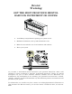
Bristol Training GET THE MOST FROM YOUR BRISTOL BABCOCK INSTRUMENT OR SYSTEM • Avoid Delays and problems in getting your system on-line • Minimize installation, start-up and maintenance costs. • Make the most effective use of our hardware and software. • Know your system. As you know, a well-trained staff is essential to your operation. Bristol Inc. offers a full schedule of classes conducted by full-time, professional instructors.
A Few Words About Bristol Inc. For over 100 years, Bristol® has been providing innovative solutions for the measurement and control industry. Our product lines range from simple analog chart recorders, to sophisticated digital remote process controllers and flow computers, all the way to turnkey SCADA systems. Over the years, we have become a leading supplier to the electronic gas measurement, water purification, and wastewater treatment industries.
For technical questions regarding ACCOL products, OpenBSI Utilities, UOI and all other software except for ControlWave and OpenEnterprise products, call (860) 945-2286. For technical questions about Network 3000 hardware, call (860) 945-2502. You can e-mail the Application Support Group at: bsupport@bristolbabcock.com The Application Support Group maintains an area on our web site for software updates and technical information. Go to: www.bristolbabcock.
CI-ControlWave EFM ControlWave EFM Electronic Flow Meter INSTALLATION FORWARD NOTE for all ControlWave EFM Installers: READ THIS SECTION FIRST! This manual has been designed for the following audience: • Customer Site Engineers, who must plan for the installation and implementation of the ControlWave EFM. • Instructors who must become familiar with and teach Field Engineers/Technicians on the installation, operation and repair of ControlWave EFM.
CI-ControlWave EFM ControlWave EFM Electronic Flow Meter TABLE OF CONTENTS SECTION TITLE PAGE # Section 1 - ControlWave EFM INTRODUCTION 1.1 1.2 1.3 1.3.1 1.3.2 1.3.2.1 1.3.2.2 1.3.2.3 1.3.2.4 1.3.2.5 1.3.3 1.3.3.1 1.3.3.2 1.3.3.3 1.3.3.4 1.3.3.5 1.3.4 1.3.5 1.3.6 1.3.6.1 1.3.6.2 1.3.6.3 1.3.6.4 1.3.7 1.3.8 1.3.9 1.3.10 1.3.11 1.3.12 1.3.13 1.3.14 1.3.15 1.4 1.5 1.5.1 1.5.2 1.5.2.1 1.5.2.2 1.5.2.3 1.5.2.3.1 1.5.2.3.2 1.5.2.4 1.5.3 1.5.3.1 GENERAL DESCRIPTION ............................................
CI-ControlWave EFM ControlWave EFM Electronic Flow Meter TABLE OF CONTENTS SECTION TITLE PAGE # Section 1 - ControlWave EFM INTRODUCTION (Continued) 1.5.3.2 1.5.3.3 1.5.3.4 1.5.4 1.5.5 1.5.5.1 1.5.6 1.5.6.1 1.5.6.2 1.5.6.3 1.5.7 Daily Historical Data Log ............................................................................................ 1-24 Periodic Historical Data Log ........................................................................................ 1-25 Alarm and Event Storage........
CI-ControlWave EFM ControlWave EFM Electronic Flow Meter TABLE OF CONTENTS SECTION TITLE PAGE # Section 2 - INSTALLATION & OPERATION (Continued) 2.3.1.1 2.3.1.2 2.3.1.3 2.3.2 2.3.3 2.3.3.1 2.3.3.2 2.3.3.3 2.3.3.4 2.3.3.5 2.3.3.6 2.3.4 2.3.4.1 2.3.4.2 2.3.4.3 2.3.4.4 2.3.4.4.1 2.3.4.5 2.3.4.5.1 2.3.4.6 2.3.4.6.1 2.3.4.7 2.3.4.7.1 2.3.5 2.3.6 2.3.7 2.3.7.1 2.3.8 2.3.9 2.3.9.1 2.3.9.2 2.3.9.3 2.3.9.3.1 2.3.9.3.2 2.3.9.4 2.3.9.5 2.3.10 2.3.11 2.4 2.4.1 2.4.2 2.4.2.1 2.4.2.
CI-ControlWave EFM ControlWave EFM Electronic Flow Meter TABLE OF CONTENTS SECTION TITLE PAGE # Section 2 - INSTALLATION & OPERATION (Continued) 2.4.2.3 2.4.3 2.4.4 2.4.5 2.4.5.1 Remote Upgrade of ControlWave EFM Firmware ................................................... 2-58 Operation of the Mode Switch...................................................................................... 2-59 Soft Switch Configuration and Communication Ports ...............................................
CI-ControlWave EFM ControlWave EFM Electronic Flow Meter TABLE OF CONTENTS SECTION TITLE PAGE # Section 4 - SPECIFICATIONS (Continued) 4.3.3 4.3.4 4.4 4.4.1 4.4.2 4.4.3 4.4.4 4.5 4.6 4.7 4.8 Power Supply External Power Monitor Specs. ............................................................ 4-3 System Controller Module Connectors.......................................................................... 4-3 INPUT/OUTPUT MODULE SPECIFICATIONS.........................................................
CI-ControlWave EFM ControlWave EFM Electronic Flow Meter TABLE OF CONTENTS SECTION TITLE PAGE # REFERENCED OEM MANUALS (Continued) Expansion Comm. Module Piggy-back Modem/Radio OEM Manuals (Continued) Internal FreeWave Radio (wired to Polyphaser) - Spread Spectrum Data Transceiver FreeWave Spread Spectrum Wireless Data Transceiver User Manual - V5.0R (model FGR09CSU) Contact the FreeWave Tech Support group @ 303-444-3862 or at www.freewave.com to request the latest copy of the user manual.
CI-ControlWave EFM ControlWave EFM Electronic Flow Meter TABLE OF CONTENTS SECTION TITLE PAGE # REFERENCED OEM MANUALS (Continued) External Modem/Radio OEM Manuals (Continued) MDS iNET 900 Ethernet Radio MDS iNET 900 Wireless IP/Ethernet Transceiver – User Guide = MDS 05-2806A01, Rev. D, Aug. 2003 (PDF = 2806D-iNET_User-web.pdf) for iNET 900 Ethernet Radio Center Insert (Installation Reference Chart) = (PDF = 2873D-iNET_Center_Sheet.
Section 1 ControlWave EFM INTRODUCTION 1.1 GENERAL DESCRIPTION ControlWave EFM electronic flow meters measure differential pressure, static pressure and temperature for a single run and compute flow for both volume and energy. In addition to operation in an unprotected outdoor environment, the ControlWave EFC electronic flow meter provides the following key features.
generated on the CPU Module (derived from the regulated 3.3Vdc logic power). In addition to Idle and Watchdog LEDs, there are six status LEDs located on the SCM that will display run time status information.
Figure 1-2A - 4-Slot ControlWave EFM (Internal View) Component Identification Diagram (Shown with D-Type Local Port) CI-ControlWave EFM Introduction / 1-3
Figure 1-2B - 8-Slot ControlWave EFM (Internal View) Component Identification Diagram (Shown with Circular Local Port) 1-4 / Introduction CI-ControlWave EFM
Figure 1-3 - 8/4-Slot ControlWave EFM (Electronic Flow Meter) Base Assemblies (The 4-Slot Chassis is shown with ECM Modules in Slots 3 & 4) 1.2 ControlWave PROGRAMMING ENVIRONMENT The ControlWave programming environment uses industry-standard tools and protocols to provide a flexible, adaptable approach for various process control applications in the water treatment, wastewater treatment, and industrial automation business.
ControlWave EFM units provide an ideal platform for remote site automation, measurement, and data management in the oil and gas industry. The control strategy file created and downloaded into the controller is referred to as a ControlWave project. The ControlWave EFM ships from Bristol Babcock with a standard ControlWave project, pre-configured for gas flow measurement, already loaded and ready to run.
function blocks accomplish various tasks common to most user applications including alarming, historical data storage, as well as process control algorithms such as PID control. The OPC Server (Object Linking and Embedding (OLE) for Process Control) allows real-time data access to any OPC [Object Linking and Embedding (OLE) for Process Control] compliant third-party software packages.
1.3.1 Enclosure ControlWave EFMs are housed in a standard Hoffman® Enclosure. External dimensions (excluding added hardware and Cover Latches) are approximately 14.56” high, by 12.97” wide, by 8.31” deep. When present, the Multivariable Transducer adds 2.89” to the height of the unit. The enclosure consists of two pieces, the body and the Instrument Front Cover. A continuous gasket seals the unit when the Instrument Front Cover is closed.
Backup Battery Jumper JP1 (on the Battery Backup Board) from position 1 to 2 and then storing it on either pin. If the Real-time clock looses its battery backup a ControlWave Designer system variable bit (_QUEST_DATE) is set. This bit can be used to post a message or alarm to the PC (see the ‘Systems Variables’ section of the ControlWave Designer Programmer’s Handbook D5125).
1.3.2.1 CPU Module Connectors The CPU Modules contain up to seven connectors that function as follows (see Table 1-1): Table 1-1 - CPU Board Connector Summary Ref. P1 P2 P3 J2 J3 J4 J5 # Pins 76-Pin 36-pin 44-pin 10-Pin 9-pin 9-pin 9-pin Function Factory Debug Card Edge Backplane I/O Bus Intf. Card Edge Backplane SCM Intf.
memory is 32-bits wide. System Firmware and the Boot Project are stored here. No hardware write protection is provided for the FLASH array. System Memory (SRAM) The base version of the CPU Module has 2Mbytes of soldered-down static RAM, implemented with two 512K x 16 asynchronous SRAMs that are configured as a 512K x 32-bit array. During power loss periods, SRAM is placed into data retention mode (powered by a backup 3.0V lithium battery). SRAMs operate at 3.3V and are packaged in 44-pin TSOPs.
Table 1-3 - Assignment of CPU Bd.
The power supply operates from +4.5/+4.9 to +16Vdc or +9.6/10.3 to +16Vdc with the nominal input supply configuration (+6V or +12V) user configured via on-board jumpers. A supervisory circuit monitors the incoming power and the supply voltages. The isolated supplies are shut down when the incoming voltage drops below +4.5V for a +6V system or +9.6V, for a +12V system. An external battery monitor is composed of an Analog to Digital Converter (ADC) and interface circuitry.
1.3.3.1 SCM Mode Switch SCM Module’s Mode Switch (SW1), is a 2-position piano type DIP-Switch that is utilized for recovery mode and core updump operations (see Sections 2.4.3 and 3.6) 1.3.3.2 SCM Board Fuse The SCM is fused to protect the entire system. 5x20mm Slow Blow Fuse F1 is rated at 1A. 1.3.3.3 SCM Board Connectors Connectors TB1, TB2, J1, J2 and P2 function as described below. SCM Bd. Terminal Block Connector TB1 TB1 provides 3 input connections for bulk power: TB1-1 = +VIN (+4.5/4.9 to +16.
1.3.4 ControlWave EFM Backplanes 4-Slot or 8-Slot ControlWave EFM Backplanes provide for the electrical interconnection of the System Controller Module (SCM), CPU Module, Expansion Communication Modules (ECOMs) and/or I/O Modules. One or two Expansion Comm. Modules may be substituted for I/O Modules in Backplane slots 3 & 4. Backplane module slot connections that support Expansion Comm. Modules (slots 3 & 4) or I/O Modules (slots 3 through 8) are implemented via 36-pin female Headers.
The unit’s Base Assembly Chassis is mounted to the Fabrication Panel inside the Hoffman Enclosure. ControlWave EFM Chassis’ contain a Ground Lug that accommodates up to a #4 AWG Ground Wire. Grounding the unit is accomplished by connecting a ground wire between the Ground Lug and a known good Earth Ground. 1.3.6 ControlWave EFM I/O Modules Five unique I/O Modules are available factory configured for either local or remote field device wiring termination.
1.3.6.1 Non-isolated Analog I/O & Analog Input Modules (also see Section 2.3.4.5) ControlWave EFM AI/O Modules provide 6 Analog Inputs and optionally 2 Analog Outputs. All Analog Inputs are externally sourced, single-ended and individually Jumper configurable for either 4-20mA or 1-5Vdc. Analog Outputs are externally sourced and are individually Jumper configurable for 4-20 mA or 1-5 Vdc. 30Vdc Transorbs provide surge suppression between each signal and ground.
Figure 1-9 - ControlWave EFM Communications Module 1.3.8 Internal Mounting Brackets Internal mounting brackets that support the various system components, such as the Battery, ControlWave EFM Base Assembly, etc., are mounted on the ‘Fabrication Panel,’ which in turn is secured to the inner rear wall of the enclosure.
modem will mount via a Radio/Modem Mounting Bracket (beneath the Battery Mounting Bracket on units equipped with a 4-Slot Chassis).. 1.3.9 Multivariable Transducer The Multivariable Transducer (MVT) pressure assembly is connected to the process manifold either directly or by tubing. In the body of the transducer, metal diaphragms are exposed to the gas. Solid-state strain gauge sensors in the neck of the transducer measure the pressure applied to the diaphragms and produce proportional electrical signals.
Figure 1-11 - Digital To Relay I/O Board 1.3.12 21V Power Supply Option The 21V Power Supply is a continuous mode boost switching type power supply. It is based upon a low power, low noise circuit that produces 21 Volts from a 12V input. Power shutdown is not an option with this unit since it employs a Boost circuit; therefore, the 21V Power Supply must be powered continuously.
Solar panels mount to a 2" pipe and can be swiveled for optimum alignment with the sun and their tilt angle is adjustable for maximum performance to accommodate the latitude of the installation site. Solar panel wires enter the unit through a liquid tight conduit fitting on the bottom of the enclosure. Internally the solar panel wires connect directly to the rechargeable battery - PWR (red wire) and GND (black wire) terminals. 1.3.
• • • • • • AGA7 with selectable AGA8 Gross or AGA8 Detail Auto Adjust AGA7/NX-19 Auto Adjust AGA7 with selectable AGA8 Gross or AGA8 Detail Includes run switching Includes an auto-selector, PID flow/pressure control algorithm per run or per station Interfaces to a chromatograph and provides energy throughput as well as composition information (requires the optional Expansion Communications Module) Resides on a BSAP SCADA network Supports samplers and odorizers Provides audit trail and archives Includes a
totals, and archive averages. The user can select AGA3/NX-19 (1985), AGA3/AGA8, AGA7/NX-19 or AGA7/AGA8. 1.5.2.1 Flow Rate and Flow Time Calculations (AGA3) For orifice flow measurement, the differential pressure value is compared to a flow cutoff value every second. If the differential pressure is less than the flow cutoff value, flow is considered to be zero for that second.
or an external MVT, the user selects the downstream tap location during MVT configuration, the MVT firmware changes the sign of the differential pressure to provide a positive DP value. 1.5.3 Archives The ControlWave EFM stores two distinct types of archive data. The first type is Audit Trail data, which is a recording of the various events and alarms that have an impact on the calculated and reported rates and volumes.
The following items are stored in the Daily Data Log. • • • • • • • • • • Corrected Volume Uncorrected Volume Accumulated Energy Average Static Pressure Average Temperature Average Differential Pressure Average Specific Gravity Average Heating Value Flow Time Uncorrected Count Each log entry also contains the date and time. The ControlWave EFM has a Daily Historical Log for each of four runs. 1.5.3.3 Periodic Historical Data Log The periodic data log holds one record for every log interval.
1.5.5 Communications A ControlWave EFM can be configured as a Master or Slave node on either a MODBUS network or a BSAP network. Up to three communication ports are contained on the ControlWave EFM CPU Module and are designated as follows: CPU Module: COM1 - Port 1: COM2 - Port 2: COM3 - Port 3: CPU Bd. J3, PC/AT 9-Pin Male D-Sub - RS-232 CPU Bd. J4, PC/AT 9-Pin Male D-Sub - RS-232 CPU Bd.
slave transmit and receive data on opposite lines; all slaves (from the first to the "nth") are paralleled (daisy chained) across the same lines. The master node should be wired to one end of the RS-485 cable run. A 24-gauge paired conductor cable, such as Belden 9843 should be used. Note: Only half-duplex RS-485 networks are supported. From the factory COM1 defaults to 115.2 kbd using the BSAP Protocol. The remaining serial communication ports, i.e.
1.5.6.2 Pulse Output for External Totalizer or Sampler When the ControlWave EFM is configured to provide a pulse output based on volume, the operator provides a control volume and pulse duration. After each calculation cycle, an internal volume accumulator is compared to the control volume. If the accumulator exceeds the control volume then a pulse is output and the accumulator is reduced by the volume represented by the pulse.
Section 1A PRODUCT FEATURES & OVERVIEW 1A.1 PRODUCT OVERVIEW ControlWave® products have been designed and integrated as a highly adaptable, high performance Distributed Open Controller family with exceptional networking capability that provides a complete Process Automation Management Solution. ControlWave EFM electronic flow meters have been designed with an emphasis on providing high performance with low power consumption, scalability and modularity.
• • • • Full user programming environment, ControlWave Designer with ACCOL III, is available for modification of existing loads as well as creation of custom loads Full suite of function blocks for flow calculations, audit trail, historical archive/data management, communication, and process control is included. File management, including video images Fully supported by a complete HMI and network communication software suite: Bristol Babcock’s OpenBSI 1A.
Briefly, this library includes function blocks for: • • • • • Average, Compare, Totalize Scheduling & Sequencing PID & Lead/Lag AGA gas flow and liquids calculations File handling In addition, ControlWave ensures data integrity, in the event of a communication interruption, by storing critical time-stamped alarm and historical data in the controller memory. This data is then securely retrieved when communication is restored. 1A.
other client applications communicate with the Bristol networks. OpenBSI supports both serial BSAP protocol and Ethernet Internet Protocol communication to ControlWave and Network 3000 RTUs and controllers. 1A.3.2 OpenBSI Utilities Above this communication layer are a group of applications known as OpenBSI Utilities.
1A.3.3.1 ActiveX Controls • • • • • Security - 56-bit encryption - allows the user to sign on to the RTU Signal Value - displays signal values in various formats Comm.
class hardware and software with confidence in their interoperability. Our OpenBSI OPC Server was among the first to comply with the OPC Foundation alarm and event server specification. • • • • • • • • • • • OPC Data Access 1.0a & 2.
• • • • • • • Global time-synchronization Time-stamped Alarm reporting Historical archive data transfer Audit file transfer On-line program editing Diagnostics Communication statistics 1A.4.1.2 Modbus Protocol Modbus - Modbus is often considered a de-facto standard protocol because broad usage as either the primary or a secondary offering in many measurement and control related products. Even with its common use, Modbus protocol actually has many variations.
BLANK PAGE
Section 2 INSTALLATION & OPERATION 2.1 INSTALLATION IN HAZARDOUS AREAS Each ControlWave EFM electronic flow meter is furnished in a housing designed to meet the NEMA Type 3 specifications and to operate in a Class I, Division 2, Groups C & D environment with a nonincendive rating (see Appendix A).
Figure 2-1B - 8-Slot ControlWave EFM (Shown with MDS - Transnet Radio & Circular Local Port) 2-2 / Installation & Operation CI-ControlWave EFM
Each ControlWave EFM Base Assembly (4/8-Slot) is housed in an open-faced Gold Irridite coated Aluminum Chassis assembly. Keyed cutouts in rear wall of the ControlWave EFM Base Assembly are provided for Wall or Panel mounting arrangements.
ControlWave EFM Modules that comprise the system are housed in a base assembly consisting of an open faced Gold Irridite coated Aluminum Chassis equipped with either a 4-Slot or 8-Slot Backplane. Dimensional drawings of the Base Assemblies are provided at the end of Chapter 4. 2.2 SITE LOCATION CONSIDERATIONS Check all clearances when choosing an installation site. Make sure that the ControlWave EFM Instrument Front Cover (hinged on the left side) can be opened for wiring and service.
1. Remove the unit from its carton and install it at the assigned work site (see Section 2.3.1). Dimensions are provided in Section 4.6 of this manual. 2. Remove the SCM Module and after configuring its jumpers, install it into ControlWave EFM Base Assembly, chassis slot 1, i.e., the first slot from the left end of the Base Assembly Chassis (see Section 2.3.2). 3. Remove the CPU Module. Make sure that the Lithium Backup Battery has been enabled, i.e.
Step 3. Establish Communications using either LocalView or NetView, and Run the Flash Configuration Utility Communications must be established with the ControlWave EFM using either LocalView or NetView. The ControlWave EFM ships from the factory with a default Flash configuration. Most users will need to edit this configuration to set the BSAP local address (IP address if using PPP), user accounts, and port parameters.
Once the program has been created, it is assigned to an executable task. The entire project is then saved and compiled. NOTE: From this point on, the order of steps may be varied, somewhat, depending upon the requirements of the user's application. NOTE: If you modify the standard EFM program, you may need to modify the standard web pages associated with it. (See Step 5, below). Step 5.
2.3.1 Mounting the ControlWave EFM Enclosure When mounting one of these units, it is to be positioned in accordance with the following restrictions: - The unit is to be positioned vertically with the Multivariable Transducer (MVT) at its base and is to be mounted to a wall or a vertical 2” pipe (clamed at the rear of the unit via two clamps and four bolts). If used, the 2” pipe is to be anchored in cement (deep enough to conform to local building codes associated with frost considerations).
- There should be clearance for the optional Solar Panel (if required) (the Solar Panel may be mounted to the same 2” pipe that secures the unit. Power wiring should not be installed until the unit has been mounted and grounded at a designated work site. I/O wiring, external power wiring, RTD cabling, local comm. port, antenna cable, and network (RS-232 and RS-485) comm. port cabling enter the bottom of the unit though conduit or special function fittings.
2.3.1.1 Connection to the Multivariable Transducer (MVT) One Multivariable Transducer (MVT) is provided with each ControlWave EFM and is secured to the bottom of the enclosure. Figure 2-5 details MVT process flange and optional manifold block connector mounting dimensions. The MVT provides connection ports on the process flange as the standard arrangement. Optional manifold blocks may also be specified.
Optional Process Manifold Blocks: Process manifold blocks may be installed on the transmitter to permit the use of connector assemblies having different connection centers. The manifold blocks, which are oval in appearance, mate with the transmitter's process flange. The blocks may be installed in several positions to achieve different connection centers as shown in Figure 2-5. MVT Interface Cable.
by cathodic protection or other EMF on the pipeline. ControlWave EFMs may be mounted directly on the pipeline (see Figure 2-6) or remotely on a vertical stand-alone two-inch pipe (see Figure 2-7). It is recommended that isolation fitting always be used in remotely mounted meter systems.
heating (e.g., with a rose-bud torch) it electrically insulates and increases the strength of the pipe stand. See Bristol Specification Summary F1670SS-0a for information on PGI Direct Mount Systems and Manifolds. 2.3.2 System Controller Module (SCM) Configuration System Controller Module’ (SCM) configuration jumpers must be set to configure bulk power (+6Vdc or +12Vdc nominally) and to enable or disable the Power Good LED (see Figure 2-8). The SCM is installed in Backplane slot #1 (see Figure 2-2).
For safety reasons and to prevent accidental damage to a user supplied external bulk DC Power Supply, it is recommended that pluggable Terminal Block connector TB1 be disconnected from the SCM until the entire unit has been wired, and hardware configured. Sections 2.3.9.1 & 2.3.9.2 provide details on DC Power Connector TB1 wiring.
SW2-3 set OFF forces the use of Soft Switches as set per factory default (see Section 2.4.4). For use of user defined Soft Switches, SW2-3 must be set to the ON position. Note: If both SW2-3 and SW2-8 are set OFF (closed), all communication ports will be set to 9600 bps operation (8-bits, no parity, 1 stop bit, BSAP Protocol). SW2-4 set OFF and used in conjunction with the SCM Mode switch will cause the ControlWave EFM to perform a Core Updump (see Section 3.6).
Table 2-3 - CPU Bd. Switch SW1 - Force Recovery Mode/Battery Enable Switch Function Setting - (OFF = Factory Default) ON = Force recovery mode (via CW Console) SW1-3 Force Recovery Mode OFF = Recovery mode disabled Note: SW1-1, SW1-2 and SW1-4 are not used. 2.3.3.2 Communication Ports A ControlWave EFM can be configured as a Master or Slave node on either a MODBUS network or a BSAP network. A variety of communication schemes are available.
Up to three communication ports are contained on the ControlWave EFM CPU Module and are designated as follows: CPU Module: COM1 - Port 1: CPU Bd. J3, PC/AT 9-Pin Male D-Sub - RS-232 - connected to Local Port COM2 - Port 2: CPU Bd. J4, PC/AT 9-Pin Male D-Sub - RS-232 - supports External Radio COM3 - Port 3: CPU Bd.
Expansion Communications Module 1: Resides in Base Chassis Backplane Slot #3 COM4 - Port 1: ECOM Bd. J1, PC/AT 9-Pin Male D-Sub - RS-232 COM5 - Port 2: ECOM Bd. J2, PC/AT 9-Pin Male D-Sub - RS-485 Expansion Communications Module 2: Resides in Base Chassis Backplane Slot #4 COM8 - Port 1: ECOM Bd. J1, PC/AT 9-Pin Male D-Sub - RS-232 COM9 - Port 2: ECOM Bd.
Figure 2-12 - Communication Port RS-232 Cable Wiring Diagram CI-ControlWave EFM Installation & Operation / 2-19
Table 2-4A - RS-232 Ports (1/2/4/8) and RS-485 Ports (3/5/9) Pin Assignments Pin Signal Description: Signal # RS-232 RS-232 Signals RS-485 1 DCD Data Carrier Detect Input 2 RXD Receive Data Input RXD3 TXD Transmit Data Output TXD4 DTR Data Terminal Ready Output TXD+ 5 GND Signal/Power Ground GND/ISOGND* 6 DSR Data Set Ready Input RXD+ 7 RTS Request To Send Output 8 CTS Clear To Send Input * ISOGND on Isolated RS-485 Ports Only! Note: Pin-9 not used Description: RS-485 Signals N/A Receive Data - Input Trans
Figure 2-13B - PC Connected to ControlWave EFM via Circular Local Port Bristol Cable Part Number 395402-01-8 = 10 Foot Comm. Cable Bristol Cable Part Number 395402-02-6 = 25 Foot Comm. Cable RS-485 Ports ControlWave EFM can use an RS-485 communication port for local network communications to multiple nodes up to 4000 feet away. Since this interface is intended for network communications, Table 2-5 provides the appropriate connections for wiring the master, 1st slave, and nth slave.
by configuring CPU Bd. Switch SW3 and/or ECOM Switch SW1 (COM6/COM9) so that the 100-Ohm termination resistors and biasing networks are installed at the end nodes and are removed at all other nodes on the network (see Table 2-6).
Installation steps 1 through 3 below support user installation and configuration of a Spread Spectrum Modem. 1. Mount the radio (Spread Spectrum Modem) onto the Expansion Comm. Module. Remove the nut and washer from the internal coaxial RF cable supplied with the ECOM Module. Remove the plug from the front of the ECOM Cover and insert the in-ternal coaxial RF cable’s SMA connector (straight end with flat area on top) through the rear of the ECOM Cover.
Figure 2-14 - Expansion Comm.
Modems are supplied in kit form with all the hardware required for user installation onto an Expansion Communications Module. Figure 2-14 shows the modem mounted on the Expansion Comm. Module. Modems are user installed onto the ECOM Module (see Figure 2-14) and their associated Ports are setup during installation in the Ports Page of the Flash Configuration Utility. The Flash Configuration Utility is accessed via NetView or LocalView.
Complies with Part 68 FCC Rules. Contains device with FCC Registration Number: AU7-USA-25814-M5-E Ringer Equivalence Number (REN): 0.3B Note: The sum of all the RENs on your telephone lines should be less than five in order to assure proper service from the telephone company. In some cases, a sum of five may not be usable on a given line. • Any direct connections to PSTN lines must be made through standard plugs and jacks as specified in the FCC rules. The PSTN line connector plugs into J1 on the modem.
Figure 2-16 - Wiring for Phone Cord Connector 2.3.3.6 Radio Ready and External (Case Mounted) Modem or Radio A wide selection of modems and radios are offered. The ControlWave EFM is factory shipped with a user selected radio or modem installed within the enclosure (beneath the Battery Mounting Bracket) or as a radio ready unit, i.e., ready for field installation of a Bristol supplied radio.
removable Terminal Block connectors and field devices (see Figure 2-18). Use AWG 14 or smaller wire, (consult with the field device manufacturer for recommendations). Leave some slack and plan for wire routing, identification, maintenance, etc. The bundled wires are to be routed in/out through the bottom of the I/O Module Assembly between the Terminal Block Assembly and the Terminal Housing Assembly. All I/O wiring should be routed in/out of the enclosure through 1” NPT Conduit Hub.
6. Using a PC equipped with ‘ControlWave Designer’ and ‘OpenBSI’ software, configure the ControlWave EFM to accept the new I/O Module (and any other modules that have been added or removed) and then download the application load into the ControlWave EFM CPU’s System FLASH and/or SDRAM (see Section 2.4.1). For new installations, this step can be skipped until the unit has been wired and power applied.
2.3.4.2 I/O Wire Connections ControlWave EFM electronic flow computers utilize compression-type terminals that accommodate up to #14 AWG wire. A connection is made by inserting the wire’s bared end (1/4” max) into the clamp beneath the screw and securing the screw. The wire should be inserted fully so that no bare wires are exposed to cause shorts. If using standard wire, tin the bare end with solder to prevent flattening and improve conductivity.
Figure 2-19 - Non-Isolated DI/O Module Configuration Diagram 2.3.4.5 Non-isolated Analog Input/Output & Analog Input Modules (see Figure 2-20) Analog Input/Output Modules support six 4-20mA or 1-5 Vdc single ended analog inputs and optionally, two independently configurable 4-20mA or 1-5 Vdc analog outputs. AI/O Modules consists of an Analog Input/Output PCB with two 10-point Terminal Block Assemblies (for local termination), 12 Configuration Jumpers and a Cover Assembly.
Each AI signal is channeled through signal conditioning circuitry (that provides a 2 Hertz low pass filter), a transorb for surge suppression, multiplexer, and an A to D Converter (ADC).
The Analog Output circuit consists of a 12-bit resolution Digital to Analog Converter (DAC), a V to I circuit, and a V to V circuit. The 12-bit DAC dives the V to I circuitry. A scaling circuit within the V to I circuit drives the V to V circuitry. V to I and V to V circuitry are powered by an external power source. A CPLD generates the control signals for the ADC, multiplexer, EEPROM, Bus Interface and E2PROM that contains the calibration data. 2.3.4.5.
Modules consists of a High Speed Counter PCB with two 10-point Terminal Block Assemblies (for local termination), 14 Configuration Jumpers, an LED Board with 4 Status LEDs (one for each point) and a Cover Assembly. The HSC Board mates with the Backplane PCB via a 36-pin gold plated card edge connector.
signals, or relay contacts. A serial EEPROM contains HSC Board serialization data. Each input of the HSCI Module is configured as a 16-bit high-speed counter. 2.3.4.6.1 High Speed Counter Configurations HSC Modules provide a total of 4 HSC inputs with surge protection. HSC Module Configuration Jumpers W1 through W14 must be set per Table 2-10.
Figure 2-22 - Mixed I/O Module Wiring Diagram Mixed I/O Modules optionally support one externally powered (VEXT = 11 to 30Vdc) analog output. AO Circuitry consists of a 12-bit resolution Digital to Analog Converter (DAC), a V to I circuit, and a V to V circuit. The 12-bit DAC drives the V to I circuitry. A scaling circuit within the V to I circuit drives the V to V circuitry. V to I and V to V circuitry are powered by an external power source.
Figure 2-23 - Non Isolated Mixed I/O Module Configuration Diagram 2.3.4.7.1 Mixed I/O Module Configurations Mixed I/O Module Configuration Jumpers W1 through W28 must be set per Table 2-11.
Table 2-11 - Non Isolated Mixed I/O Module Jumper Assignments (Continued) Jumper W23 - W26 W27 Purpose Configures AI1 through AI4 (respectively) AO Voltage Selection Set W27 Pins 2-3 ALWAYS Notes Pins 1-2 installed = 4-20mA AI (250 ohm resistor in) Pins 2-3 installed = 1-5V AI Pins 1-2 installed = N/A Pins 2-3 installed = External Field Voltage (TB2-9) Pins 1-2 installed = HSC Circuit Enable (Powered) Pins 2-3 installed = HSC Circuit Disabled * = W1 located on optional AO Daughter Board W28 HSC Circuitr
Figure 2-25 - RTD Probe Installation/Removal Diagram 2.3.6 21V Power Supply Option 21V Power Supplies are mainly used in conjunction with Temperature and Pressure Transmitters which require a higher than +12V but lower than +21.4V (±.8V) input supply to operate (such as Series 3508 Transmitters). Figure 2-26 - 21V Power Supply Board 21V Power Supply Boards contain two terminal blocks that accommodate power connections between the ControlWave EFM and remote transmitters.
Table 2-13 - 21V Power Supply Board Terminal Designations 21VPS TB# TB1-1 TB1-2 TB1-3 TB2-1 TB2-2 TB2-3 TB2-4 21VPS TB NAME +12VIN 12VGND CHASSISGND +21V 21VGND +21V 21VGND CONNECTION to PDB. TB3-1 TB3-2 N/A N/A N/A N/A N/A CONNECTION to XMTR. N/A N/A N/A XMTR1+ XMTR1XMTR2+ XMTR2- 2.3.7 Digital to Relay I/O Board Option Digital to Relay I/O Boards except up to two discrete input signals from an open drain MOSFET device and convert them to Form C relay output signals using Solid State Relay (SSR) logic.
The commons associated with each form C Relay (R0COM and R1COM) have the option of being tied to the ControlWave EFM Power Ground or to a floating Ground. Jumper W1 is associated with Outputs R0A and R0B and W2 is associated with outputs R1A and R1B. When Jumper W1 is installed the common (C) associated with Outputs R0A and R0B is tied to ControlWave EFM Power ground; when Jumper W1 is not installed, the common will be floating.
Figure 2-28 - Digital to Relay I/O Board Wiring Diagram 2.3.8 Connection to a Model 3808 Transmitter A Model 3808 Transmitter (Digital) can be interfaced to a ControlWave EFM via either an RS-232 or an RS-485 communication scheme. Communication schemes and cable lengths are determined the type of communication port utilized. In general RS-232 communications are utilized when the Model 3808 Transmitter is situated within 25 feet of the ControlWave EFM, i.e., for local communications.
Note: For Loopback & Termination Control: Use SW3 on CPU Module to configure COM3. Use SW1 on ECOM Module to configure COM5 or COM9. Figure 2-30 - Model 3808 Transmitter to ControlWave EFM RS-485 Comm.
Figures 2-29 and 2-30 detail the RS-232 and RS-485 wiring connections required between the ControlWave EFM and the Model 3808 Transmitter. Up to eight (8) Model 3808 Transmitters can be connected to a ControlWave EFM via a half duplex RS-485 Network. An illustration of this network is provided in Figure 2-31. 2.3.
Power Distribution Boards are provided with six (6) Terminal Connector Blocks that function as follows: TB1 - Primary Power Input: (three-conductor) (from user supplied bulk power source) TB1-1 = Power+ (Pos. input) TB1-2 = Power– (Neg.
Bulk +6/12Vdc Supply Current = CPU* + Sum of all ECOM Modules, I/O Modules, optional Boards & Optional External Modem/Radio This summation will accommodate steady state current draw. Table 2-16 provides detailed steady state power current requirements for each ControlWave EFM Base Assembly module. Note: In the case of an external modem/radio, the unit’s manufacturer provides power consumption specifications.
2.3.9.3 Mounting an Optional Solar Panel Solar Panels (used to charge the rechargeable lead acid batteries) are to be mounted to a 2” to 2-3/8” pipe as illustrated in Figure 2-35. Muffler (Pipe) Clamps, utilized for this purpose, are secured via four 1/4-20 nuts and washers. A A B B D C E Note 2: Item D slots accommodate Tilt Angle Adjustment. A A NOTE 1: To Attach item C to item D: Slide two bolts (A) through the top and bottom Solar Panel (Centered) Channel Holes.
2.3.9.3.2 Tilt Angle 30/40 Watt Solar Panel Systems (see Figure 2-35) have adjustable tilt angles. Table 2-17 shows the angle (from horizontal) at which the Solar Panel should be installed in order to maximize annual energy output. At most latitudes, performance can be improved by less of an angle during the summer and more of an angle during the winter.
1. Remove connector TB1 from the System Control Module (SCM) and remove the Battery/Power Harness from the Battery Charger/Power Manager Board. 2. Remove the Lead-acid Battery from its shipping carton. 3. Install the Lead-acid Battery (on end) as illustrated in Figure 2-36. Note: Make sure the Lead-acid Battery is fully charged before installing it. 4. Route Solar Panel Power Wiring Harness into the enclosure through the Solar Power Conduit Fitting (see Item 5 of Figure 2-3). 5.
NOTE: If the Battery or is removed when power is off the contents of SRAM (on the CPU Module) will not be retained. Once a Battery has been removed, don’t install a replacement Battery for at least one minute unless SW2-5 on the CPU has been set OFF. 2.3.11 Installation of a Bezel Assembly (see Figure 2-2 & 2-37) Bezel Assemblies provide a protective cover and wire routing for any two ControlWave EFM I/O Modules.
2.4 OPERATIONAL DETAILS ControlWave EFM electronic flow computers are shipped from the factory with firmware that allows the unit to be configured in conjunction with an IEC 61131, application program. This section provides information as follows: - Steps required to download the application load and place the unit into ‘Run’ mode. Steps required to download system firmware.
Upgrade of system firmware via LocalView FLASH Mode requires OpenBSI 5.1 (or newer). If you have an older version of OpenBSI, FLASH upgrades are to be performed via HyperTerminal. You will need a binary (*.BIN) system firmware file, and that file should be defined in the Flash Master File (FLASH.MST). A sample Flash Master File is shown, below: cwe0420.bin where cwe is the product code and 0420 is the release # Upgrade of an unattended ControlWave EFM can be accomplished from a remote PC.
When the "Mode", "Name", and "Location" have been specified, click on the [Create] push button to activate the Communication Setup Wizard. Step 1 - Communication Setup Choose the communication port you want in the What port would you like to use: field. Click on the [Next] pushbutton to activate the next wizard. Figure 2-39 - Communication Setup: Step 1 Menu Step 2 - Flash RTU Setup In the Flash RTU Setup Wizard, you need not set the RTU type or local address, since these are unused in this mode.
Step 3 - Flash Data Setup Complete the following fields in the Flash Data Setup Wizard: "Please enter the name of the binary file to Flash" To upgrade system firmware, you must specify the path and name of a binary (*.BIN) file on your hard disk containing the firmware. Click on [Finish] to install the specified BIN file in FLASH memory at the RTU.
Once the Flash download has begun, you will NOT be allowed to shut down LocalView, unless you cancel the download, or it has been completed. The progress of the Flash download will be displayed in the window. Any mismatch in file versions, or if the type of .BIN file does not match the type of RTU, the download will be aborted. Once the download has completed, disable Recovery Mode by setting System Controller Module switch SW1 as follows: SW1-1 set OPEN (Right) and SW1-2 set CLOSED (Left).
6. Close the HyperTerminal program. The null modem cable connected between the ControlWave EFM and the PC can be removed if desired. 7. Set the System Controller Module’s Mode Switch (SW1) for ‘Local Mode,’ i.e., SW1-1 in the OPEN (Right) position and SW1-2 in the CLOSED (Left) position. Switch Power OFF and then ON again. If CPU Module Switch SW1 was set for Recovery Mode, set SW1-3 OFF.
Once the ControlWave EFM running its application load, status codes are posted to the six Status LEDs on the PSSM. These Status LED (Hex) Codes are listed in Table 2-15 (see Figure 2-47.
Table 2-18 - System Status LED Codes on System Controller Module Status In Hex 00 01 03 04 05 07 08 09 0A 0B 10 11 12 20 28 30 38 3B 3E 3F LED LED LED LED LED LED 6 5 4 3 2 1 0 0 0 0 0 0 0 0 0 0 0 0 0 1 1 1 1 1 1 1 0 0 0 0 0 0 0 0 0 0 1 1 1 0 0 1 1 1 1 1 0 0 0 0 0 0 1 1 1 1 0 0 0 0 1 0 1 1 1 1 0 0 0 1 1 1 0 0 0 0 0 0 0 0 0 0 0 0 1 1 0 0 1 0 0 1 0 0 1 1 0 0 1 0 0 0 0 1 1 1 0 1 1 0 1 1 0 1 0 1 0 1 0 0 0 0 0 1 0 1 Indication Definition Application Running Unit in Diagnostic Mode Unit Running
2.4.3 Operation of the Mode Switch The System Controller’s Mode Switch (SW1) is a two position piano type DIP-Switch that functions as follows: Both switches set to the OPEN (Right) or CLOSED (Left) positions = Recovery Mode. Recovery Mode is used for either a firmware upgrade (see Section 2.4.2) or a core updump (see Section 3.6). SW1-1 set to the OPEN (Right) position and SW1-2 set to the CLOSED (Left) position = Local Mode. Local Mode should be selected for normal running operations. 2.4.
WINDIAG program, it must not otherwise be in use. Note: CPU Switch SW2-8 must be set OFF to run the WINDIAG program. In lieu of the use of an RS-232 Port, an RS-485 cable (see Tables 2-4A & 2-5) can be connected between COM5 and the PC’s RS-485 Port. COM8: From the factory, RS-232 Communications Port COM8 on the second optional Expansion Communications Module defaults to 9600 baud, 8-bits, no parity, 1 stop bit, BSAP/ControlWave Designer protocol operation.
Figure 2-48 - Dual-Button Display/Keypad Assembly Installation Drawing CI-ControlWave EFM Installation & Operation / 2-61
Figure 2-49 - 25-Button Display/Keypad Assembly Installation Drawing 2.4.5.1 Operation of the Dual-button Display/Keypad Assembly The Display will have a timeout of 20 minutes. If there has been no keypad activity for this time the display will “logout,” i.e., the display will be turned off and scrolling stopped until a key press occurs. When a key press occurs after a timeout the display will return to the opening screen.
If a shorter timeout of the display is needed for power savings, another timeout may be implemented. The processor connected to the display will control the timeout. When the timeout occurs the display will be blanked, but communications between the ARM and display processor will still occur. The display processor will ignore posting the messages to the screen when in the low power mode. When a key is pressed the display processor will return to displaying information to the display.
Manual Mode In Manual Mode the programmer is responsible for creating each screen and displaying the next desired screen, based on key inputs. The programmer has access to all lines of the display and can provide any string that he/she desires to display. Special formats that must be adhered to that allow the programmer to display what they want on the screen are provided in the description of iaScrnSruct in the ACCOL 3 Display function block within ControlWave Designer’s On-Line Help.
Section 3 SERVICE 3.1 SERVICE INTRODUCTION This section provides general, diagnostic and test information for the ControlWave EFM. The service procedures described herein will require the following equipment: 1. PC with null modem interface cable & Bristol’s WINDIAG Software 2. Loop-back plug, 9-pin female D-Sub (for RS-232) (see Figure 3-9) 3. Loop-back plug, 9-pin female D-Sub (for RS-485) (see Figure 3-10) The following test equipment can be used to test the Power Supply/Sequencer Module: 1.
3.2.2 Removal/Replacement of the Bezel Assembly Before I/O Modules can be removed, the Bezel Assembly, which covers them, must be removed. 1. Grasp the sides of the Bezel Assembly and gently lift it up and then pull it out and off its associated I/O Module Covers. 2. To replace the Bezel Assembly, first align the latches (left and right, top and bottom) with the associated I/O Module Cover notches.
4. Press down on the Cover’s built-in top latch (with one hand) and up on the Cover’s built-in bottom latch (with the other hand). 5. Carefully slide the I/O Module out of the front of the Housing. If binding occurs, gently rock the I/O Module up and down to free it. 6. To replace an I/O Module, power must be off. Carefully align the I/O Module with the applicable I/O Slot and insert the unit into the Housing. When the assembly is fully seated, its cover should be latched to the Housing. 7.
Figure 3-1 - Sealed Lead-acid Battery Mounting Diagram 3.2.8 Removal/Replacement of a Power Distribution Board 1. If the ControlWave EFM is running, place any critical control processes under manual control and shut down the unit by disconnecting power to the System Controller Module (SCM). 2. Unplug wiring harnesses from Power Distribution Board connectors TB1 through TB6 (make sure cables are identified for proper replacement). 3.
3.2.9 Removal/Replacement of a 21V Power Supply Board 1. If the ControlWave EFM is running, place any critical control processes under manual control (as required). 2. Unplug wiring harnesses from 21V Power Supply Board connectors TB1 and TB2. 3. Slide the 21V Power Supply Board toward the front of the unit and remove it from its Snap Track Holder. 4. To replace a 21V Power Supply Board, slide it into its Snap Track Holder. Replace wiring harness connectors TB1 and TB2. 5.
+16Vdc), you can determine the point at which the unit turns off, i.e., the point at which the PWRGOOD LED on the SCM goes OFF (Vt-). If the value of the bulk power supply’s +6Vdc or +12Vdc output approaches the value of Vt+ or Vt- it should be replaced by a power supply with the correct +6V or +12V output.
ControlWave EFM LED designations are provided in Table 3-1.
Table 3-2 - System Status LED Codes on System Controller Module (Continued) Status (Hex) 11 12 20 28 30 38 3B 3E 3F LED 6 0 0 1 1 1 1 1 1 1 LED 5 1 1 0 0 1 1 1 1 1 LED 4 0 0 0 1 0 1 1 1 1 LED 3 0 0 0 0 0 0 0 1 1 LED 2 0 1 0 0 0 0 1 1 1 LED 1 1 0 0 0 0 0 1 0 1 Indication Definition Error Testing SDRAM Error Testing SRAM Application Loaded Stopped at a Break Point No Application Loaded Running with Break Points Waiting for Power-down (after NMI) Waiting for Updump to be Performed Unit Crashed (Watchdog
Figure 3-4 - CPU Module Communication Connector and LED Designations Figure 3-5 - ControlWave EFM Plus I/O Module LED Designations CI-ControlWave EFM Service / 3-9
Figure 3-6 - Expansion Comm. Module - Comm. Connector and LED Designations 3.3.3 Wiring/Signal Checks Check I/O Field Wires at the Card Edge Terminal Blocks and at the field device. Check wiring for continuity, shorts & opens. Check I/O signals at their respective Terminal Blocks (see Table 3-3). Table 3-3 - I/O Field Wiring - Terminal Block Reference List I/O Subsystem Digital I/O Analog I/O HSC Inputs Mixed I/O Figures 2-19 2-20 2-21 2-22 Notes See Section 2.3.4.4 See Section 2.3.4.5 See Section 2.3.4.
3.4.1 Extent of Field Repairs Field repairs to a ControlWave EFM are strictly limited to the replacement of complete modules. Component replacement on a ControlWave EFM Module constitutes tampering and will violate the warranty. Defective ControlWave EFM Housings or Modules must be returned to Bristol Inc. for authorized service. 3.4.2 Disconnecting RAM Battery The ControlWave EFM’s Lithium RAM battery cannot be replaced while power is on.
COM2: From the factory, RS-232 Communications Port COM2 on the CPU Board defaults to 9600 baud, 8-bits, no parity, 1 stop bit, BSAP/ControlWave Designer protocol operation. To test COM2 using the WINDIAG program, it must not otherwise be in use and CPU Switch SW2-8 must be set OFF. COM3: RS-485 Communications Port COM3 on the CPU Board defaults to 9600 baud, 8bits, no parity, 1 stop bit, BSAP/ControlWave Designer protocol operation.
Figure 3-7 - Netview Startup Menu - Example with Multiple Networks Figure 3-8 - WINDIAG Main Diagnostics Menu CI-ControlWave EFM Service / 3-13
4. Select the module to be tested. Enter any prompted parameters (slot #, etc.). WINDIAG will perform the diagnostics and display pass/fail results. 5. After all diagnostic testing has been performed, exit the WINDIAG program and then exit the Netview Program if there aren’t any other ControlWave EFM units to be tested. When you close the Netview program you will be prompted as to whether or not you want to close the OpenBSI program; select Yes. 6.
Figure 3-9 - RS-232 Loop-back Plugs Figure 3-10 - RS-485 Loop-back Plugs Figure 3-11 - WINDIAG’s Communications Diagnostic Menu 1. Type "1," "2," "3," or "4" for the port to test. 2. Set baud rate to test to 115200 baud or ALL ASYNC and the number of passes to 5.
3. Click on RUN button next to External loop-back. Test responses: a) Success - All sections of test passed b) Failure - TXD RXD Failure or CTS RTS Failure Execution time < 5 sec. 3.6 CORE UPDUMP In some cases a copy of the contents of SRAM and SDRAM can be uploaded to a PC for evaluation by Bristol Inc. engineers. This upload is referred to as a ‘Core Updump.
Section 4 SPECIFICATIONS 4.1 CPU, MEMORY & PROGRAM INTERFACE Processor: Sharp’s LH7A400 32-bit ARM9TDMI RISC Core System-on-Chip with 32-bit Memory: 8 Mbytes of simultaneous read/write FLASH 2 Mbyte of on-board SRAM 512 Kbytes FLASH Boot/Downloader Real Time Clock: A Semtech SH3000 support IC provides a full BCD clock calender with programmable periodic/wakeup interrupt and a programmable clock generator with adjustable spectrum spreading.
Table 4-2 - RS-232 Ports (COM1/2/4/8 and RS-485 Ports COM3//5/9 Connector Pin Assignments Pin # 1 2 3 4 5 6 7 8 9 Signal RS-232 DCD RXD TXD DTR GND DSR RTS CTS Description: RS-232 Signals Data Carrier Detect Input Receive Data Input Transmit Data Output Data Terminal Ready Output Signal/Power Ground Data Set Ready Input Request To Send Output Clear To Send Input N/A Signal RS-485 RXDTXDTXD+ ISOGND RXD+ Description: RS-485 Signals N/A Receive Data - Input Transmit Data - Output Transmit Data + Output Iso
Shutdown: +6V System: Max. ON Switchpoint = 4.90V Min. OFF Switchpoint = 4.33V +12V System: Max. ON Switchpoint = 10.3V Min. OFF Switchpoint = 9.28V 4.3.2 Power Supply Sequencer Specs. Signals Monitored: Input Power Sequencer Switchpoints: +3.3V Max. ON Switchpoint = +3.15V +3.3V Min. OFF Switchpoint = +3.00V +1.8V Max. ON Switchpoint = +1.72V +1.8V Min. OFF Switchpoint = +1.
Figure 4-2 - SCM - TB1 (Power Connector) 4.4 INPUT/OUTPUT MODULE SPECIFICATIONS 4.4.
Note2: 2.5 ohm uncompensated series resistance with Inductors Terminations: Pluggable - Max. wire size is 14 gauge Data Transfer: 8 Bit Wide bus access 4.4.2 Non-isolated Digital Input/Output Module Non-isolated Digital Inputs Number of Inputs: 12 DI individually jumper configurable for 2mA or 60uA Internally Sourced (Dry Contact) operation Input Filtering: 15 milliseconds Input Current: Jumper configured for 2mA or 60uA nominal ‘0’ State Voltage: below 1.5V ‘1’ State Voltage: above 1.
4.4mA @ 3.3Vdc: 12 DIs ON @ 66uA, CLK active 27.6mA @ 3.3Vdc: 12 DIs ON @ 2mA, CLK active Status LEDs Enabled All DIs and DOs OFF: 33uA All DIs and DOs ON: add 32mA Terminations: Pluggable, max wire size is 14 gauge for local terminations Two 14-pin mass termination headers are provided for remote terminations 4.4.
2 High Speed Counter Inputs per Module 1 Analog Output (optional) per Module Terminations: Pluggable - Max. wire size is 14 gauge Power Consumption: 5mA Base Current @ 3.3V Non-isolated Mixed I/O Module Digital Inputs/Outputs Number of Points: Up to 6 individually jumper configurable DI/O Input Current: Individually Jumper selectable input current of 60uA or 2mA Input Configuration: Internally Sourced Dry Contact Input Filtering: 30 milliseconds ‘0’ State Voltage: below 1.
Power Consumption: 2.5mA + 1.145mA @ 4.66US/Channel Period, CLK active 180uA, CLK stopped Non-isolated Mixed I/O Module Analog Output Number of Outputs: 4-20mA Output Compliance: 1 AO (1-5V or 4-20Ma) jumper configurable 250 ohm load with 11V External Power Source 650 ohm load with 24V External Power Source 1-5V Output: 5mA maximum output current into external load with external voltage range of 11 to 30 Vdc Accuracy: Current Output: 0.1% of Span @ +25ºC (+77ºF) 0.
Electrical isolation: None Surge Suppression: 31V Transorb between signal and ground Meets ANSI/IEEE C37.90-1978 Status Indication: None Power Consumption: 200uA or 2mA per HSCSET or HSCRST Input (ON State) (Jumper Selectable per Point) (Clock Power Disabled - Subtract 1.1mA @ 3.3V) 4.5 DIGITAL TO RELAY I/O BOARD SPECIFICATIONS Digital to Relay I/O Board General Specs. Terminations: Pluggable - Max.
Vibration: 1g for 10Hz to 500Hz per PMC-31-1 (without damage or impairment) 21V Power Supply Board Performance Specifications Input Voltage (Vin): 10.8V to 16V (dc) Input Current (Iin): 100mA (Typ. @ 12V & 50mA load) 140mA (Max. over Temp. Range @ 50mA load) Output Voltage (Vout): 21.4Vdc ±0.8V Output Current (Iout): 50mA (Max.) Ripple/Noise: 20mV (Max. P-to-P) Efficiency: 88% (Typ.) Fuses: F1 = 500mA (Slow Blow): Protects host power source from failures within the 21V Pwr. Supply Bd.
Figure 4-3 - 4-Slot ControlWave EFM Base Chassis Assembly Dimensions CI-ControlWave EFM Specifications / 4-11
Figure 4-4 - 8-Slot ControlWave EFM Base Chassis Assembly Dimensions 4-12 / Specifications CI-ControlWave EFM
Figure 4-5 - ControlWave EFM NEMA 3X Enclosure Dimensions CI-ControlWave EFM Specifications / 4-13
BLANK PAGE
ControlWave EFM Special Instructions for Class I, Division 2 Hazardous Locations 1. 2. 3. 4. 5. 6. 7. 8. 9. 10. 11. 12. 13. Bristol, Inc.’s ControlWave EFM Electronic Flow Meter is listed by Underwriters Laboratories (UL) as nonincendive and is suitable for use in Class I, Division 2, Group C and D hazardous locations or nonhazardous locations only. Read this document carefully before installing a nonincendive ControlWave EFM Electronic Flow Meter.
ControlWave EFM Special Instructions for Class I, Division 2 Hazardous Locations Table A1 -Module/Board Connector Customer Wiring Connectors (Continued) Module/Item Connector SCM Module SCM Module Exp. Comm Module 1 TB1 - Input Power TB2 - RTD Interface J4 - COM4, 9-pin Male D-sub RS-232 J5 - COM5, 9-pin Male D-sub RS-485 Exp. Comm Module 1 Exp. Comm Module 2 J8 - COM7, RJ11 Female J4 - COM8, 9-pin Male D-sub RS-232 J5 - COM9, 9-pin Male D-sub RS-485 Exp.
Appendix C HARDWARE INSTALLATION GUIDE Hardware Configuration There are seven (7) main steps required to configure a ControlWave EFM. This appendix provides an overview of these steps with an emphasis on the installation and configuration of the hardware. This appendix is intended for users who have already installed at least one ControlWave EFM. Step 1.
Figure C-1B - 8-Slot ControlWave EFM (Internal View) SCM & CPUM Installed in Slots #1 & #2 (Respectively) of Base Assembly C-2 / Appendix C - Hardware Installation Guide CI-ControlWave EFM
Step 1. Hardware Configuration (Continued) 2. Remove the System Controller Module (SCM) and after configuring its configuration jumpers, install it in chassis slot 1, i.e., the first slot from the left end of the Base Assembly Chassis (see Section 2.3.2). WATCHDOG LED (Red) CR27 JP5, JP6, JP7, JP8 & JP9 1-to-2 Installed = 12V Bulk System 2-to-3 Installed = 6V Bulk System IDLE LED (Red) Staus LEDs (Red) CR26 CR25 CR24 1 JP6 JP7 1 1 JP5 JP8 1 JP9 1 SW1 = Mode Switch J2 Display Intf.
Table C-1 - CPU Bd. Switch SW1 - Force Recovery Mode/Battery Enable Switch Function Setting - (OFF = Factory Default) Force Recovery ON = Force recovery mode (via CW Console) SW1-3 Mode OFF = Recovery mode disabled Note: SCM Switch SW1 can also be used for Force Recovery Mode operation Table C-2 - CPU Bd.
A ControlWave EFM can be configured as a Master or Slave node on either a MODBUS network or a BSAP network. Up to three communication ports are contained on the ControlWave EFM CPU Module and are designated as follows: CPU Module: COM1 - Port 1: COM2 - Port 2: COM3 - Port 3: CPU Bd. J3, PC/AT 9-Pin Male D-Sub - RS-232 CPU Bd. J4, PC/AT 9-Pin Male D-Sub - RS-232 CPU Bd.
Expansion Communications Module: COM4, COM5, COM6 & COM7 on 1st ECOM Bd., - assigned to Base Housing Slot #3 COM8, COM9, COM10 and COM11 on 2nd ECOM Bd., assigned to Base Housing Slot #4 COM4/8 - Port 1: ECOM Bd. J1, PC/AT 9-Pin Male D-Sub - Both RS-232 COM5/9 - Port 2: ECOM Bd. J2, PC/AT 9-Pin Male D-Sub - Both RS-485 COM6/10 - Port 3: ECOM Bd. Piggy-back Radio Module (FreeWave or MDS TransNet Spread Spectrum Modem) Antenna connector provided (Optional) COM7/11 - Port 4: ECOM Bd.
Radios are user installed onto the ECOM Module (see Figure C-4A) and their associated Ports are setup during installation in the Ports Page of the Flash Configuration Utility. The Flash Configuration Utility is accessed via NetView or LocalView. FreeWave® Spread Spectrum Wireless Data Transceiver: Operates in the 902 to 928 MHz range (20 miles).
Figure C-4B - ECOM Module Component Identification Diagram #2 Microwave Data System Inc. MDS TransNET OEM™ Spread Spectrum Data Transceiver: Operates in the 902 to 928 MHz range (20 miles). Installation steps below support user installation and configuration of a Spread Spectrum Modem. • Mount the radio (Spread Spectrum Modem) onto the Expansion Comm. Module. Remove the nut and washer from the internal coaxial RF cable supplied with the ECOM Module.
Figure C-5 - Communication Port RS-232 Cable Wiring Diagram CI-ControlWave EFM Appendix C - Hardware Installation Guide / C-9
• For FreeWave Radio: Follow the Tuning Transceiver Performance” section of the FreeWave Technologies Inc. FreeWave Spread Spectrum Wireless Data Transceiver User Manual to configure the radio. For MDS Radio: Refer to section 3.3 “Initial Power-Up & Configuration” within the MDS TransNet OEM Integration Guide and if necessary for more information on connecting a PC terminal and preparing it for use, refer to section 9.0 “PROGRAMMING REFERENCE.
Base Housings - Slots 3 & 4 (in lieu of Expansion Comm. Modules) & Slots 5 through 8 Expansion Housings - Any Slot Install I/O wiring to each I/O Module (see Figures C-6 through C-10). Install a communications cable between the ControlWave EFM and a Model 3808 Transmitter (Network of Transmitters) if required (see Figures C-11 & C-12).
Figure C-7 - Non-isolated AI/O Module Configuration Diagram C-12 / Appendix C - Hardware Installation Guide CI-ControlWave EFM
Figure C-8 - Non Isolated HSC Module Configuration Diagram Step 1. Hardware Configuration (Continued) 6. Install a ground wire between the Chassis Ground Lug and a known good Earth Ground (also see Supplement Guide S1400CW). ControlWave EFM Housings are provided with a Ground Lug that accommodates up to a #4 AWG wire size. A ground wire must be run between the Chassis Ground Lug and a known good Earth Ground.
connected to Chassis Ground when they have been installed and secured via their two Captured Panel Fasteners. As an extra added precaution, it is recommended that a #14 AWG wire be run from SCM Power Connector TB1-3 (Chassis Ground) to the same known good Earth Ground. The following considerations are provided for the installation of ControlWave EFM system grounds.
Figure C-10 - Non-isolated Mixed I/O Module Wiring Diagram (see Figure C-9 for Mixed I/O Module Configuration Diagram) • Chassis Ground Lug to Earth Ground wire size should be #4 AWG. It is recommended that stranded copper wire is used and that the length should be as short as possible. • This ground wire should be clamped or brazed to the Ground Bed Conductor (that is typically a stranded copper AWG 0000 cable installed vertically or horizontally).
• The wire ends should be tinned with solder prior to insertion into the Chassis Ground Lug. Note: Use a high wattage Soldering Iron. • The ground wire should be run such that any routing bend in the cable has a minimum radius of 12-inches below ground and 8-inches above ground Step 1. Hardware Configuration (Continued) 7. Install the Bezel/Bezels so that the I/O Modules are covered. 8. Install RTD (wiring and Probe) (see Section 2.3.5 of this manual). 9.
Figure C-12 - ControlWaveEFM to 3808s - RS-485 Network Diagram Step 2. Software Installation on the PC Workstation ControlWave Designer software will have to be installed on the PC if the ControlWave EFM is to be utilized in an application other than that supported by the standard load. This is accomplished by installing the ControlWave Designer Package from the Open BSI CD ROM. You must install the Open BSI Network Edition.
Step 3. Establish Communications using either LocalView or NetView, and Run the Flash Configuration Utility Communications must be established with the ControlWave EFM using either LocalView or NetView. The ControlWave EFM ships from the factory with a default Flash configuration. Most users will need to edit this configuration to set the BSAP local address (IP address if using PPP), user accounts, and port parameters.
Once the program has been created, it is assigned to an executable task. The entire project is then saved and compiled. NOTE: From this point on, the order of steps may be varied, somewhat, depending upon the requirements of the user's application. If you modify the standard EFM program, you may need to modify the standard web pages associated with it. (See Step 5, below). Step 5.
Downloading the Application Load Any ControlWave EFM must have a configured application load before it can be placed into operation. For units not shipped with the ‘Standard Load,’ this will require connection of the ControlWave EFM to a PC running Windows NT (4.0 or higher), Windows 2000 or Windows XP Professional and equipped with ControlWave Designer software & OpenBSI software. Configuration of the application load must be performed by an individual familiar with the various programming tools.
Table C-6 - LED Assignments Module LED Name SCM * SCM * SCM CPUM CPUM CPUM CPUM CPUM CPUM ECOM1 ECOM1 ECOM1 ECOM1 ECOM1 ECOM1 ECOM1 ECOM1 ECOM2 ECOM2 ECOM2 ECOM2 ECOM2 ECOM2 ECOM2 ECOM2 IDLE WD 6 STATUS C1 RX (Comm 1) C1 TX (Comm 1) C2 RX (Comm 2) C2 TX (Comm 2) C3 RX (Comm 3) C3 TX (Comm 3) C1 RX (Comm 4) C1 TX (Comm 4) C2 RX (Comm 5) C2 TX (Comm 5) Radio RX (Comm 6) Radio TX (Comm 6) Modem RX (Comm 7) Modem TX (Comm 7) C1 RX (Comm 8) C1 TX (Comm 8) C2 RX (Comm 9) C2 TX (Comm 9) Radio RX (Comm 10) Radio
Figure C-13 - SCM Status LED Hexi-decimal Codes C-22 / Appendix C - Hardware Installation Guide CI-ControlWave EFM
Appendix D ECOM MODULE RADIO/MODEM INSTALLATION GUIDE D1.1 RADIO INSTALLATION & CONFIGURATION D1.1.1 Installing an Internal FreeWave Radio (FGR09CSU) FreeWave Radio Model GR09SCU is provided (for user installation) in a kit consisting of the following components: • • • • • 2-56 x .188” Pan Head Screw (Qty. 3) - Fig. D2 Reference = 1 2-56 x .250” F/F Standoff (Qty. 3) - Fig. D2 Reference = 2 2-56 x .250” Pan Head Screw (Qty. 3) - Fig. D2 Reference = 3 FreeWave Radio Cable (with Nut and Washer) - Fig.
Figure D1 – Expansion Comm. Module Component Identification Diagram D1.1.2 Configuring the FreeWave Radio (FGR09CSU) To configure a Model FGR09SCU Radio (installed on an Expansion Communication Module), perform the following eight (8) steps: 1. If required, remove the Exp. Comm. Module from the unit in question (see Figure. D1). 2. Place the radio into configuration ode by setting Expansion Comm. Module Jumper JP2 onto pins 1 and 2. This will enable configuration of the radio through Comm.
Figure D2 - FreeWave Radio Installation Diagram CI-CW MICRO/CW EFM Appendix D - Radio/Modem Installation Guide / D-3
4. Open Hyperterminal on the PC and set the PC communication port settings as follows: Bits per second: Data bits: Parity: Stop bit: Parity Check: Carrier Detect: Flow Control: 19200 8 None 1 None/Off None/Off Xon/Xoff 5. Cycle power to the ControlWave MICRO/ControlWave EFM. The FreeWave configuration menu will appear in Hyperterminal. 6. In the configuration menu, set the radio as a multipoint slave. Go to the edit book and type in the serial number of the Master Radio to which you want to communicate.
NOTE: ECOM Module Comm. Ports 4/8 (RS-232) are wired the same as CPU Module Comm. Ports OPTION Populated by Order 1 If In Slot #3 Comm. Port Assignments If In Slot #4 1 J11 2 2 1 3 3 1 5 2 2 4/8 3 3 4 MDS Transnet Radio Kit Parts 6/10 Cover Panel EMI Gasket 1 = 6-32 x .188” Pan Head Screw (Nylon) (Qty. 4) 2 = 6-32 x .313” F/F Standoff (Nylon) (Qty. 4) 3 = 6-32 x .250” Pan Head Screw (Qty. 4) 4 = MDS Transnet Radio Cable (with Nut and Washer) 5 = MDS Transnet Radio Module Exp Comm.
To install a MDS Transnet OEM Radio onto an Expansion Comm. Module, perform the following nine (9) steps (referring to Figure D-4): 1. Remove the Expansion Comm. Module from the unit in question (see Figure D1). 2. Grasp the Expansion Comm. Module with one hand. Squeeze both sides of the Cover Panel (just below the unit’s top) and pull up and away to release the Cover Panel and EMI Gasket from the PCB (see Figure D2). Note: If necessary, a small screwdriver can be used to pry the Cover Panel from the PCB.
Parity Check: Carrier Detect: Flow Control: None/Off None/Off Xon/Xoff 4. Cycle power to the ControlWave MICRO/ControlWave EFM. After hitting the escape (Esc) key and then the carriage return twice (at approximately half second intervals), the right arrow (>) will appear. 5. In the configuration menu, set the radio mode using either the MODE M (master) or MODE R (remote) command. Note: There can be only one Master radio per network.
Figure D5 - MultiTech Modem Installation Diagram D-8 / Appendix D - Radio/Modem Installation Guide CI-CW MICRO/CW EFM
6. Snap the Cover Panel onto the Expansion Comm. Module PCB and insert the ECOM Module into the appropriate Backplane Slot, i.e., Slot 3 or 4. 7. Apply power and test the unit. D2.1.2 Configuring the MultiTech Modem (MT5634SMI) To configure a Model MT5634SMI Modem (installed on an Expansion Communication Module), perform the following nine (9) steps: 1. If required, remove the Exp. Comm. Module from the unit in question (see Figure D1). 2. Place the modem into configuration mode by setting Expansion Comm.
BLANK PAGE
Instruction Manual CI-ControlWave EFM & CI-ControlWave MICRO Oct., 2006 ControlWave EFM & MICRO ControlWave EFM/MICRO DISPLAY/KEYPAD ASSEMBLY - GUIDE Appendix E www.EmersonProcess.
APPENDIX E ControlWave MICRO/EFM Display/Keypad Assembly Guide TABLE OF CONTENTS SECTION TITLE E1.1 E2.1 E2.1.1 E3.1 E4.1 E4.1.1 E4.1.2 E4.1.3 E4.1.3.1 E4.1.3.2 E4.1.4 E4.1.5 E4.1.6 E4.1.7 E5.1 OVERVIEW ................................................................................................................... E-1 DISPLAY FUNCTION BLOCK DESCRIPTION......................................................... E-2 DISPLAY Function Block Parameters .......................................................
Appendix E DISPLAY/KEYPAD ASSEMBLY GUIDE E1.1 OVERVIEW Bristol, Inc. Display/Keypad assemblies provide a built-in, local, user interface for the ControlWave MICRO or the ControlWave EFM. These assemblies allow an operator or engineer to view and modify variable values and associated status information, via an ACCOL3 Function Block. Variables can include inputs, process variables, calculated variables, constants, setpoints, tuning parameters and outputs used in a measurement or control application.
Display/Keypad Assemblies are supported by Automatic Mode and Manual Mode. Automatic Mode In Automatic Mode a set of screens (based on the application load) are displayed. The application programmer provides strings for the opening screen. From there the firmware is responsible for displaying the screens and responding to key presses. Screens are fixed and start off with an opening screen, which displays user information passed into the function block.
Figure 2 - ACCOL3 DISPLAY Function Block Parameters E3.1 PREPARING THE ControlWave PROJECT In order for the keypad and display to operate, the ControlWave Designer project must include a properly configured Display Function Block. Once the Keypad is operating, a user who has signed on with a password can scroll through the names of variable lists and choose a list to read or change. Use Up Arrow and Down Arrow keys to select the Username and use the numeric keys to enter your password.
Figure 3 - Creating the Identifier Message Step 2: Defining a Scroll List Once the keypad is operating properly, you can automatically scroll through a list of variables created via DISPLAY Function Block Parameters iiList2Scroll and iiListMode. Scrolling can be done without entering a password. The variables in the list are displayed one at a time and in the same order in which they were entered in the variable list. Later, we'll discuss other variable lists that can be accessed with the keypad.
Note 1 : If your display shows something else, press the [F4] key until you see the words Login and Scroll on the bottom line. If your screen is blank, turn the brightness screw clockwise. This screw is located to the left of the Keypad (looking at the rear of the 25-Button Display/Keypad Assembly (see Figure 17). If no letters appear, the controller has not been programmed properly to operate the keypad. The words Login and Scroll at the bottom of the screen are on the legend line.
variable name appears on the first line. The variable value appears on the second line and status information appears on the third line. An example is shown in Figure 6. When all variables in the list have been displayed, they will be shown again in the same order. This is called Single Variable Mode. Pressing Mlti [F2] activates Multiple Variable Mode. Multiple Variable Mode displays up to three (3) variables and their values on the screen simultaneously.
Figure 7 - Logging On Once the correct password has been entered, the display will look like Figure 7C. When the second line shows READ/WRITE, you can read and write variable parameters. When it shows READ ONLY you cannot change variable parameters. You are only permitted to read variable information. If your display shows READ ONLY and you want to change variable values, sign-off (press the [INIT] key) and log on with a username and password that provides Read/Write privileges.
Figure 8 - Clock Display E4.1.3.1 Changing the Time From the display shown in Figure 8, press Time [F2]. Colons (:) will appear on the third line. Enter the new time there and press [ENTER]. Valid times range from 00:00:00 to 23:59:59. Invalid entries will be ignored. The display will be updated to show the new time. Figure 9 - Time Set Display If you make a mistake while entering the new time, use [DEL] to backspace and delete one character at a time. E4.1.3.
SCROLL function from the Initial Display. The variable name and value are presented from the Scroll List. This function is available to all users even without signing-on. The List Menu will show other groups of variable which you can choose to read. This information will be more detailed than the Scroll List. To get to the List Menu, choose MENU (press [F2]) from the Logged-On Display (Figure 7C).
Before making any changes, first check the signal inhibit status field (See Figure 12). When the display shows ME (manual enable) you can change variable parameters. When it shows MI (manual inhibit), you cannot alter the parameters of this variable. If the field indicates MI, press the OPER I/E key to change it to ME. To change an analog value: Press CHNG (F3) to clear the third line. Use the number keys 0 through 9 to enter the new value. The minus sign and period are also permitted. Press [ENTER].
Notes for Figure 12 1. Variable Name (Example 1: @GV.FLOW_RATE) (Example 2: @GV.TOTAL_FLOW_RATE) 2. Value - analog value, string value, or logical value. Values which cannot fit in this field will be shown as asterisks. Analog values are displayed in floating point format, for example, 0.0125, 99.627, and 1287.66. When the value cannot be shown in floating point format, scientific format is used (1.287668E+10 or 1.25E-02 for example). 3.
Notes for Figure 12 (Continued) Variables are shown below as they would appear in SNGL mode. 1) String SITE_NAME WEST SUNBURY PUMP STATION CE ME 2) Analog TOTAL_FLOW_RATE 1260.578 CE MI 3) Logical FLOW_ALARM OFF CE MI AE NA E4.1.7 Signing-Off Once you have logged-on, use the [INIT] key at any time to log-off. When this key has been pressed, the screen will look like Figure 13. Press Yes (F1) to sign-off. You are signed-off when the Identifier Display (Figure 3C) appears.
E5.1 KEYPAD IDENTIFICATION & INSTALLATION INFO. 10 1 5.50 5.50 3.25 3.13 .19 1.13 .313 .31 TYP 1.25 .75 2.750 .43 7.38 .06 2.13 2.00 .25 MAX TYP. .25 1.25 4.19 .06 6.500 .50 .75 10 .190 .170 4.69 7.38 1 3.625 .
Figure 15 - 25 Button Keypad Table 1 - 25 Button Keypad Keys KEY F1, F2, F3, F4 INIT 0 to 9, -, • Δ ∇ ALM I/E ALM ACK A/M OPER I/E DEL ENTER FUNCTION Function keys will take on a variety of different functions depending on the situation. The function of these keys is listed on the legend line (bottom line) of the display. The INIT key is used to terminate the keyboard session and sign-off. These keys are used to change the value of analog variables in the CONFIGURATION mode.
Instruction Manual CI-ControlWave EFM Oct., 2006 Using ControlWave EFM WebBSI Web Pages Appendix F www.EmersonProcess.
BLANK PAGE
APPENDIX F ControlWave EFM Using ControlWave EFM WebBSI Web Pages TABLE OF CONTENTS SECTION TITLE F.1 F.1.1 F.2 F.2.1 F.3 F.4 F.4.1 F.4.1.1 F.4.1.2 F.4.2 F.4.3 F.5 F.5.1 F.5.2 F.5.2.1 F.5.2.2 F.5.3 F.5.4 F.5.4.1 F.5.4.1.1 F.5.4.1.2 F.5.4.1.3 F.5.4.1.4 F.5.4.1.5 F.5.5 F.5.5.1 F.5.5.2 F.5.5.3 F.5.5.4 F.5.6 F.5.6.1 F.5.6.2 F.5.7 F.5.7.1 F.5.7.2 F.5.7.3 F.5.7.4 F.5.7.5 F.5.7.6 F.5.7.7 F.6 F.6.1 F.6.1.1 F.6.1.2 GENERAL OVERVIEW .................................................................................
APPENDIX F ControlWave EFM Using ControlWave EFM WebBSI Web Pages TABLE OF CONTENTS SECTION TITLE F.6.2 F.6.2.1 F.6.2.2 F.6.2.3 F.6.2.4 F.6.3 F.6.3.1 F.6.3.1.1 F.6.3.1.2 F.6.3.1.3 F.6.3.2 F.6.4 F.7 F.7.1 F.7.2 F.7.3 F.7.4 F.7.5 F.8 F.8.1 F.8.2 F.8.3 F.8.4 F.9 F.10 Meter Run I/O Configuration.......................................................................................F-23 Differential Pressure, Static Pressure and Temperature Inputs ..............................F-23 Frequency Input ...........
Appendix F Using ControlWave EFM WebBSI Web Pages F.1 GENERAL OVERVIEW The ControlWave EFM is configured and monitored using WebBSI Web pages developed specifically for the standard application program. The Web pages are stored and displayed on a personal computer (PC), and use either OpenBSI Network edition or Local edition to interface to the ControlWave EFM.
PC/Laptop Computer ControlWave EFM Figure F-1 - ControlWave EFM Connected to PC via the Local Communications Cable F.2.1 Communication Connections The ControlWave EFM communicates with the PC through the Local Port as shown in Figures F-1 through 2B. The Local Port has been provided specifically for installation, startup and on-site configuration and data collection.
Figure F-2B - PC Connected to ControlWave EFM (via Circular Local Port) Bristol Cable Part Number 395402-01-8 = 10 Foot Comm. Cable Bristol Cable Part Number 395402-02-6 = 25 Foot Comm. Cable F.3 WebBSI PROGRAM STARTUP Ensure that the Local Communications Cable connections (at both the ControlWave EFM & the PC) are secure.
F.4.1 Signing On/Off When the WebBSI Web pages for the ControlWave EFM are first accessed, the SIGN On/Off Web page is displayed. A user must select the RTU Name from the drop down menu. If using OpenBSI Network Edition, this drop down menu will include all nodes available on the network. If using OpenBSI Local Edition, only the default node (RTU) will be available. Figure F-3 - Sign On/Off Web Page F.4.1.
The Node Locator Web page is accessible by clicking on the Security category button and choosing the Locate Nodes drop-down menu selection. Figure F-4 - Locate Nodes Web Page F.4.3 Contacts A list of Bristol Inc. offices is provided under the topic Contacts. The Contacts Page is accessible by clicking on the Security category button and choosing the Contacts drop-down menu selection. F.
Figure F-5 - Station Summary Web Page F.5.2 Sampler and Odorizer Configuration See section F.5.2.1 for Sampler Configuration or F.5.2.2 for Odorizer Configuration. F.5.2.1 Sampler Configuration The user may enable or disable the Sampler by using the Enable/Disable button. If enabled, the Sampler will operate at a frequency set by the Pulse Frequency setpoint (in cubic feet). Users must select which Digital Output (DO) Point will be used. A running count of samples taken will be displayed.
When the Digital Output Mode is used, the user must enter the frequency of the pulses per volume through the meter (in cubic feet). Figure F-6 - Sampler & Odorizer Configuration Web Page F.5.3 Mechanical Counter Configuration The Mechanical Counter Configuration section of the Sampler & Mechanical Counter Configuration Web Page is used to simulate a mechanical counter. An Enable/Disable button is used to activate/deactivate this function.
F.5.4 Nomination Figure F-8 - Nomination Web Page Users configure the nominations control from the Nomination WebPage. Nominations functionally provide the user with the ability to set the ControlWave EFM to allocate precise amounts of gas flow during specific time periods. These periods are called “nomination periods.” A nomination may be set for any duration of time (not to exceed one month). The volume to be delivered (nominated) during a nomination period is the target.
arrive at the target (volume or energy) as quickly as possible without regard to the programmed end time. Flow Control The Flow Control method internally enables the PID flow control algorithm in order to hit the target volume/energy at exactly the programmed end time. The user programs the ControlWave EFM t(via the ‘Stop Mode’ button) to either close the valve upon reaching the target or leave it in its last position. F.5.4.1 Nomination Operation See sections F.5.4.1.1 through F.5.4.1.5. F.5.4.1.
this signal to end an in progress nomination immediately, or to start the next period immediately (see Manually Starting/Ending a Nomination Period). Stop Mode The Stop mode selection allows the user to automatically have the valve closed, i.e., shut-in on stop mode, or left in the last position upon reaching the target (or programmed end period). Daily Only Mode When Daily mode is enabled, only the programmed start and end hours are used by the ControlWave EFM; the Start/Stop days are ignored, i.e.
Percent Delivered This signal provides the percentage of target delivered to this point in the current nomination period. NEXT NOMINATION PERIOD - This section allows the operator to set/view the following parameters associated with the next nomination which is to be programmed (has been programmed): Note: New entries must be made prior to the ending of the current nomination period.
F.5.4.1.3 Ending a Nomination Period If shut-in on stop mode is in use, the current period will end when the target accumulation is reached. At this time, the ControlWave EFM attempts to close the control valve. If PID control is being used, the setpoint is set to 0.0, the current cycle will ramp down accordingly. When the flow rate reaches 0.0, the current cycle accumulations and the actual end time are copied into the LAST signals.
property damage, and injury to persons. When setting the WebBSI Web Page parameters, make sure the associated process is observed and protected. Figure F-9 - Flow Control & Valve Control Web Page Setpoint (x1000) This field contains the operating point at which the flow rate is to be controlled. Set-point units are MSCFH with a default setting of 1000 MSCF per Hour. To change the Setpoint value, right click on the field and select Change Signal Value.
Max Flow Rate (x1000) Max Flow Rate represents the maximum flow rate allowed. If the number entered in the Setpoint field exceeds the Max Flow Rate value, the Max Flow Rate value will be used. To change the Max Flow Rate (x1000) value, right click on the field and select Change Signal Value. Valve Travel Time Valve Travel Time is the amount of time it takes a Control Valve to go from being fully open to fully closed (or visa-versa). The default value is 30 Seconds.
entering a new value. When the mode is changed back to Automatic, the valve control starts from the last Manual value entered for Bumpless transfer. If the user selects Raise Lower Mode, the DO associated with raising the valve must be selected and a separate DO must be selected for lowering the valve. When the Raise Lower Mode is being used, the Current Data section will display if the Raise DO is Off’ or Raising and it will display the Lower DO state, i.e., Off or Lowering.
Figure F-10 - Run Switching Web Page F-16 / Appendix F CI-ControlWave EFM
F.5.7 Radio Control The Radio Control Configuration Web Page is accessible for users by selecting Radio Control.
F.5.7.1 Radio Control Mode Enable/Disable Radio Control via a control button to the right of Radio Control Mode. F.5.7.2 Common Properties Local Address Local Address of the ControlWave EFM is set via the RTU Configuration Parameters Page in NETVIEW or LOCAL VIEW. Group Number Group Address of the ControlWave EFM. This is set via the RTU Con-figuration Parameters Page in NETVIEW or LOCAL VIEW.
Re-Calculate Next On Time If the user makes any changes to the items that affect the On Time, it must re-calculate the Next On Time using this button. Next On Time Hour/Minute/Second When the Radio Control Mode is selected for Hourly, Daily or Daylight, these values represent the next time that the radio will be turned on. Turn Off Delay Seconds Turn Off Delay Seconds is the amount of time (in seconds) that the radio will remain enabled after successful communications have been established and completed.
Figure F-12 - Meter Run Type Configuration WebPage F.6.1.1 AGA3 - Orifice Meter If the meter is configured as an Orifice Meter the following Read Only items are displayed: Pipe Diameter & Orifice Diameter – To change these items, select Flow Equation from the left side menu section.
Figure F-13B - Meter Run Overview (1992 AGA3 – Orifice Meter) Web Page DP (Differential Pressure), SP (Static Pressure) and T (Temperature) – Live Values from the Transmitters being used for calculation (selected via the I/O Configuration Page). Active Flow Calculation – (AGA3I (1992) or AGA3 (1985) – To change an item, select Flow Equation from the left side menu section. Current Heating Value – The instantaneous value is provided. Flow Rate (x1000) – The instantaneous value is provided.
Reset Meter Run’s Measurement Type – This button (bottom of menu) allows the user to reset the meter run’s measurement type (if a mistatke hass occurred during configuration). F.6.1.
There are five fields that allow the user to make changes: Contract Hour – Users enter the Contract Hour for the start of the Contract Day here. Current Heating Value (Units) – The user may select the Heating Value units from a drop down menu; default units are BTU/Ft3. Flow Rate (Units) – The user may select the Flow Rate units from a drop down menu; default units are Ft3/Hour. Energy Rate (x1000000) – The user may select the Energy Rate - Energy Units from a drop down menu; default units are BTU.
If a Zeros & Spans Button is pressed an Analog Input Configuration Web Pge Menu will appear (see Figure F16A). Zero, Span and Units can be configured for analog inputs 1 through 3. The Analog Input Configuration Web Page also allows the user to enable/disable the Damping function.
F.6.2.2 Frequency Input The frequency input must be brought into one of the two high-speed counter (HSC) inputs on the I/O board. Users select the two I/O points to which the typical turbine, PD, or ultrasonic meter is connected. However; if using an Invensys Auto-Adjust Turbo-Meter, both HSC inputs are used to select the Auto-Adjust Algorithm. To select the Auto-Adjust Algorithm, the user will toggle the push button under Source fromr High Speed Counter to Auto Adjust Module.
AGA5 is selected when the component mole % values are fed into the AGA5 equation. Source of the component mole % values is determined by settings made on the Chromatograph Setup Page.
F.6.2.4 Alarm Configuration (Accessed via Meter Run I/O Configuration) Figure F-17 - Alarm Configuration Web Page (Accessed from Meter Run I/O Configuration Web Page) Enable/Disable - the alarm function on a per point basis. Units and Current Value - are read from the I/O source. Alarm Limit - are set via the appropriate alarm limit point.
(1992) equation by toggling the push button labeled Click Here to select AGA3I (1992). F.6.3.1.2 1985 AGA3 Equation Configuration The user must configure the inputs to the equation. Pressure Tap – The user must select Pressure Tap type and location. The type is defined Flange or Tap and the location is defined as Upstream or Downstream.
FPV - Supercompressibility Factor (FPV) is displayed here. Base Temperature - Required or Contract Base Temperature is entered here (Deg. F). Base Pressure - Required or Contract Base Pressure is entered here (psig).
Figure F-18B - (1992 AGA3) Orifice Flow Equation Setup Web Page Adjust Press. - Users enter Average Barometric Pressure here (psia). Diff. Press. - Actual value in use is displayed here. Static Pressure - Actual value in use is displayed here. Temperature - Actual value in use is displayed here. Spec. Gravity - Specific Gravity of the gas being measured is displayed here. Z Flowing - Flowing compressibility Factor, Zf, generated from the AGA8 calculation referenced to upstream conditions.
Y - Expansion Factor Fpb - Pressure Base Factor Ftb - Temperature Base Factor Ftf - Flowing Temperature Facture Fpv - Supercompressibility Factor Fm - Additional Correction Factor Extension - Square Root of the product of Diff. Pressure and Static Pressure ( Reynolds Number - Computed Pipe Reynolds Number ) BCF - Base Correction (Zb/Zf) F.6.3.2 Frequency Flow Equation Setup If the user configures a meter as a linear meter, the AGA7 Calculation page appears (see Figure F-19).
Density Switch - Users may select whether a density meter or Gravitometer is used as an input to the equation. Gravitometer Press. Switch - Users may save the default value for Pressure or Volume entered in the Gravitometer Press. Used field. Gravitometer Temp. Switch - Users may use the default temperature value of the value entered in the Gravitometer Temp. Used field. Specific Gravity - Specific Gravity of the gas being measured is displayed here. FPV - Supercompressibility Factor is displayed here.
If the Base Pressure or Base Temperature differ from Standard conditions (14.73 psia, 60 ºF) and the 1992 AGA3 calculation is in use, an AGA8 Detail or AGA8 Gross module will be executed to calculate standard compressibility Zs for the defined gas composition. The calculation of Zs will be done once per minute or whenever a related gas constant changes. Users may select which Supercompressibility equation to use on a per run basis.
F.7 CHROMATOGRAPH CATEGORY FUNCTIONS The standard application program is configured for communicating with a Daniel 2251 Gas Chromatograph, via a serial MODBUS interface. Users will configure the Chromatograph interface from the “Chromatograph Setup” Web Page (Figure F-21).
F.7.1 Communication Settings Mode – Enabled/Disabled - When this signal is ENABLED, a chromatograph is present, and gas component data is provided by the chromatograph interface. When this signal is DISABLED, the fixed values for the gas component data are used. Common Fixed Data - When COMMON is selected fixed chromatograph values for all runs will come from the Stream 1 fixed values. When INDIVIDUAL is selected, fixed chromatograph values will come from the individual stream assigned to each run.
Figure F-22 - Chromatograph Component Range Setup Web Page F.8 LOGS CATEGORY FUNCTIONS Two WebBSI Web Pages are accessible under the Logs Category Section of WebBSI; these are: • • • • View Archives View Audit Trail View Signal List Archive File Collection F-36 / Appendix F (Section F.8.1) (Section F.8.2) (Section F.8.3) (Section F.8.
F.8.1 Meter Run Archive Files When View Archive has been selected, the Meter Run Archive Files WebBSI Web Page will be displayed (see Figure F-23). Meter Run Archive Files Web Pages provide three types of archive files, i.e., Hourly, Daily & 15 Minute for each of the four runs.
By clicking on the Floating Point Format button, the user may change the way Analog Values are displayed. By clicking on the File Definition button, the user can view how the archive file is configured. Additionally, the Meter Run Archive Web page provides the number of Fields Collected and Records Collected under the Stats field. F.8.2 Meter Run Audit Trail The ControlWave EFM keeps an Audit Trail Buffer capable of storing the most recent 500 Alarms and the most recent 500 Events.
Figure F-25 - Signal List Web Page F.8.4 Archive File Collection When Collection is selected, an Archive File Collection Web Page (see Figure F.26) will be displayed. Log Break Configuration buttons are provided on the Archive File Collection Web Page to enable/disable log breaks for configuration changes and Gas Chromatograph operation and configuration. Log Breaks are ‘Disabled’ by default.
F.9 LOAD/SAVE CATEGORY FUNCTION One WebBSI Web page is accessible under the Load/Save Category Section of WebBSI; this is called the Meter Run Save/Load Configuration Web page (see Figure F.27). This page allows a user to save configuration parameters from a ControlWave EFM or load a saved configuration down to a ControlWave EFM. The page opens from defaults and the information displayed is retrieved from the following file: (C:\OpenBSI\WebEFM\Config\DefaultMEFM.RCP).
A user may download a previously saved configuration to the ControlWave EFM. Users would select the file to download to the unit by clicking on the Browse button to locate it. A user would then click on Load from File. This will update the recipe with the information from the file. To load the configuration to the ControlWave EFM, the user would click on Write to RTU. By defaults the RCP files are stored in the following folder: (C:\OpenBSI\WebEFM\Config).
Figure F-28 - Sync Date & Time Web Page Display F-42 / Appendix F CI-ControlWave EFM
Instruction Manual CI-ControlWave EFM Oct., 2006 ControlWave EFM ControlWave EFM RADIO READY INSTALLATION GUIDE (P/N 721700-01-2) Appendix G www.EmersonProcess.
APPENDIX G ControlWave EFM Radio Ready Installation Guide TABLE OF CONTENTS SECTION TITLE G1.1 G2.1 G2.1.1 G2.2 GENERAL INTRODUCTION....................................................................................... G-1 RADIO INSTALLATION .............................................................................................. G-2 Installation of a Radio into a Radio Ready ControlWave EFM .................................. G-2 ADDITIONAL FreeWave INFORMATION ....................................
Appendix G RADIO READY INSTALLATION GUIDE G1.1 GENERAL INTRODUCTION ControlWave EFM Electronic Flow Meters may be ordered "Radio Equipped," or “Radio Ready.” Radio Ready units contain all hardware required to field install a Bristol provided radio except the radio and radio installation hardware (such as screws, nuts and washers.
G2.1 RADIO INSTALLATION DANGER Radios provided by Bristol, Inc. for use in the ControlWave EFM Electronic Flow Meters are approved for use in Class I, Division 2, Groups A, B, C & D hazardous locations. Radios may also be used in nonhazardous locations. The installer must be familiar with hazardous location installation guidelines before installation or maintenance is undertaken. Do not begin radio installation or service to the ControlWave EFM unless the area is known to be non-hazardous.
Figure 1 - Radio Installation - Mounting Diagram CI-ControlWave EFM Appendix G - Radio Ready Installation Guide / G-3
Figure 2 - Radio Mounting Bracket - Radio Installation Diagram 7. Plug the Radio Interface Cable into the radio’s Comm. Port. The other end of this cable should already be installed into Comm. Port 2. of the CPU Module. In the case of the FreeWave Radio, power is also supplied via the Interface Cable. 8. Remove the MDS Radio’s Power Connector from the MDS Radio in question and connect the unterminated ends of the MDS Power Cable (shipped loose with the ControlWave EFM) to the MDS Power Connector (Red = Pos.
Figure 3 - Partial View - ControlWave EFM with/without Polyphaser Installed G2.2 ADDITIONAL FreeWave INFORMATION The FreeWave Spread Spectrum Data Transceiver Model FGRM-501X005 User Manual contains in-depth details on modem parameters, operation, installation, tuning transceiver performance, and more. Copies of the FreeWave Spread Spectrum Data Transceiver Model FGRM-501X005 User Manual can be obtained from FreeWave Technologies, Inc. (electronically) by contacting their Technical Support Group.
Table 1 - Setup Menu Terminal Settings PARAMETER Baud Rate Data Rate Parity Stop Bits Parity Check Carrier Detect SETTING 19,200 8 None 1 None/Off None/Off Figure 4 - Cable Diagram for Radio to PC Interface G-6 / Radio Ready Installation Guide CI-ControlWave EFM
ControlWave EFM Material Safety Data Sheets A Material Safety Data Sheet is provided herein to comply with OSHA’s Hazard Communication Standard, 29 CFR 1910.1200. This standard must be consulted for specific requirements. Material Safety Data Sheets are provided in the order listed in Table Z-1 below.
BLANK PAGE
Gillette Environment Health and Safety 37 A Street Needham, MA 02492 Tel 781.292.8151 Page 1 of 4 MATERIAL SAFETY DATA SHEET NAME: DURACELL LITHIUM MANGANESE DIOXIDE COIN BATTERIES Effective Date: 8/8/03 Not applicable CAS NO: Rev: 3 A.
Page 2 of 4 D. — HEALTH HAZARD DATA Occupational Exposure Limits PEL’s, TLV’s, etc.) 8-Hour TWAs: Manganese Dioxide (as Mn) - 5 mg/m3 (Ceiling) (OSHA); 0.2 mg/m3 (ACGIH/Gillette) 1,2-Dimethoxyethane - 0.15 ppm (Gillette) Graphite (all kinds except fibrous) - 2 mg/m3 (synthetic, ACGIH); 15 mg/m3 (total, OSHA); 5 mg/m3 (respirable, OSHA) These levels are not anticipated under normal consumer use conditions.
Page 3 of 4 F. — EXPOSURE CONTROL METHODS Engineering Controls General ventilation under normal use conditions. Eye Protection None under normal use conditions. Wear safety glasses when handling leaking batteries. Skin Protection None under normal use conditions. Use butyl gloves when handling leaking batteries. Respiratory Protection None under normal use conditions. Other Keep batteries away from small children. G. — WORK PRACTICES Handling and Storage Store at room temperature.
Page 4 of 4 H. — EMERGENCY PROCEDURES Steps to be taken if material is released to the environment or spilled in the work area Evacuate the area and allow vapors to dissipate. Increase ventilation. Avoid eye or skin contact. DO NOT inhale vapors. Clean-up personnel should wear appropriate protective gear. Remove spilled liquid with absorbent and contain for disposal.
MATERIAL SAFETY DATA SHEET SECTION 1: PRODUCT AND MANUFACTACTURER Product name: Sealed maintenance-free lead acid batteries Manufacturer: B.B. Battery Co., Ltd. Address: Chengdong Trial Area, Huanggang, Raoping, Guangdong, P.R.China 515700 Tel: +86-768-7601001 or +86-768-7601002 Fax: +86-768-7601469 US Office: B&B Battery USA, Inc.
SECTION 4: PROTECTION EXPOSURE PROTECTION COMMENTS SKIN Rubber gloves, Apron, Safety shoes Protective equipment must be worn if battery is cracked or otherwise damaged. RESPIRATORY Respirator (for lead) A respirator should be worn during reclaim operations if the TLV exceeded. EYES Safety goggles, Face Shield SECTION 5: FLAMMABILITY DATA COMPONENTS FLASHPOINT EXPLOSIVE LIMITS Lead None None Sulfuric Acid None None Hydrogen 259* 4% - 74.
SECTION 7: CONTROL MEASURES 1. Store lead/acid batteries with adequate ventilation. Room ventilation is required for batteries utilized for standby power generation. Never recharge batteries in an unventilated, enclosed space. 2. Do not remove vent caps. Follow shipping and handling instructions that are applicable to the battery type. To avoid damage to terminals and seals, do not double-stack industrial batteries.
SECTION 9: SULFURIC ACID PRECAUTIONS INHALATION: Acid mist form formation process may cause respiratory irritation, remove from exposure and apply oxygen if breathing is difficult. SKIN CONTACT: Acid may cause irritation, burns or ulceration. Flush with plenty of soap and water, remove contaminated clothing, and see physician if contact area is large or if blisters form. EYE CONTACT: Acid may cause severe irritation, burns, cornea damage and blindness.
Supplement Guide - S1400CW Issue: 04/05 TM SITE CONSIDERATIONS For EQUIPMENT INSTALLATION, GROUNDING & WIRING A Guide for the Protection of Site Equipment & Personnel In the Installation of ControlWave Process Automation Controllers Bristol Babcock
NOTICE Copyright Notice The information in this document is subject to change without notice. Every effort has been made to supply complete and accurate information. However, Bristol Babcock assumes no responsibility for any errors that may appear in this document. Request for Additional Instructions Additional copies of instruction manuals may be ordered from the address below per attention of the Sales Order Processing Department.
Supplement Guide S1400CW SITE CONSIDERATIONS FOR EQUIPMENT INSTALLATION, GROUNDING & WIRING TABLE OF CONTENTS SECTION TITLE PAGE # Section 1 - INTRODUCTION 1.1 1.2 GENERAL INTRODUCTION ....................................................................................... 1-1 MAJOR TOPICS ............................................................................................................. 1-1 Section 2 - PROTECTION 2.1 2.1.1 2.2 2.2.1 2.2.2 2.3 PROTECTING INSTRUMENT SYSTEMS....................
Supplement Guide S1400CW SITE CONSIDERATIONS FOR EQUIPMENT INSTALLATION, GROUNDING & WIRING TABLE OF CONTENTS SECTION TITLE PAGE # Section 5 - WIRING TECHNIQUES (Continued) 5.2.2 5.2.3 5.2.4 5.2.5 5.2.6 5.2.7 5.2.8 5.2.9 5.2.10 Use of Twisted Shielded Pair Wiring (with Overall Insulation).................................. 5-2 Grounding of Cable Shields. .......................................................................................... 5-3 Use of Known Good Earth Grounds .........................
Section 1 - Overview 1.1 INTRODUCTION This document provides information pertaining to the installation of ControlWave systems; more specifically, information covering reasons, theory and techniques for protecting your personnel and equipment from electrical damage. Your instrument system affects the quality of service provided by your company and many aspects of its operational safety. Loss of instruments means lost production and profits as well as increased expenses.
Section 2 - Protection 2.1 PROTECTING INSTRUMENT SYSTEMS Electrical instrumentation is susceptible to damage from a variety of natural and man made phenomena. In addition to wind, rain and fire, the most common types of system and equipment damaging phenomena are lightning, power faults, communication surges & noise and other electrical interference’s caused by devices such as radios, welders, switching gear, automobiles, etc.
2.2.1 Considerations For The Protection of Personnel Always evaluate the site environment as if your life depended on it. Make sure that you understand the physical nature of the location where you will be working. Table 2-1 provides a general guideline for evaluating an installation site. Table 2-1 - Installation Site Safety Evaluation Guide # 1 2 3 4 5 6 7 8 9 Guide Indoor or outdoor – Dress Appropriately If outdoor, what kind of environment, terrain, etc.
Table 2-2 - Equipment Protection Site Safety Evaluation Guide (Continued) # 6 7 8 9 2.3 Guide Is there an antenna in the immediate area? How close is other equipment? Can someone safely touch this equipment and a ControlWave simultaneously? Determine equipment ground requirements.
Section 3 - Grounding & Isolation 3.1 POWER & GROUND SYSTEMS ControlWaves utilize DC power systems. AC power supplies are not provided with ControlWave units. ControlWave, ControlWave MICRO, ControlWave EFM/GFC/EFC, ControlWaveRED, ControlWaveREDIO and ControlWave I/O Expansion Racks are provided with a Ground Lug that accommodates up to a #4 AWG size wire for establishing a connection to Earth Ground.
not be suitable for a complex system of sophisticated electronic equipment. Conditions such as soil type, composition and moisture will all have a bearing on ground reliability. A basic ground consists of a 3/4-inch diameter rod with a minimum 8-foot length driven into conductive earth to a depth of about 7-feet as shown in Figure 3-1. Number 3 or 4 AWG solid copper wire should be used for the ground wire. The end of the wire should be clean, free of any coating and fastened to the rod with a clamp.
ground has been established, it should be tested on a regular basis to preserve system integrity. Figure 3-2 - Basic Ground Bed Soil Test Setup Figure 3-3 - Basic Ground Bed Soil Test Setup with Additional Ground Rods Figure 3-2 shows the test setup for ‘Good Soil’ conditions. If the Megger* reads less than 5 ohms, the ground is good. The lower the resistance, the better the earth ground.
Megger reads more than 10 ohms, the ground is considered ‘poor.’ If a poor ground is indicated, one or more additional ground rods connected 10 feet from the main ground rod should be driven into the soil and interconnected via bare AWG 0000 copper wire and 1” x ¼-20 cable clamps as illustrated in Figure 3-3). * Note: Megger is a Trademark of the Biddle Instrument Co. (now owned by AVO International). Other devices that may be used to test ground resistance are “Viboground”; Associated Research, Inc.
Figure 3-5 - Poor Soil Ground Bed Construction Diagram 3.3.2 Ground Wire Considerations ControlWave, ControlWave MICRO, ControlWave EFM/GFC/XFC, ControlWaveRED, ControlWave REDIO & ControlWave I/O Expansion Rack ControlWave Chassis are provided with a Ground Lug that accommodates up to a #4 AWG wire size. A ground wire must be run between the Chassis Ground Lug and a known good Earth Ground.
Ground, it is recommended that the unit’s Chassis Ground Terminal be connected to a conductive mounting panel or plate, a user supplied Ground Lug or a user supplied Ground Bus. The panel, lug or bus in turn must be connected to a known good Earth Ground via a #4 AWG wire. General Considerations The following considerations are provided for the installation of ControlWave system grounds: i Size of ground wire (running to Earth Ground should be #4 AWG.
For applications employing equipment that communicates over telephone lines, a lightning arrester Must Be provided. For indoor equipment the lightning arrester must be installed at the point where the communication line enters the building as shown in Figure 3-6. The ground terminal of this arrester must connect to a ground rod and/or a buried ground bed. Gas lines also require special grounding considerations.
grounded to the pipeline. If any pressure transmitters or pulse transducers are remotely mounted, connect their chassis grounds to the pipeline or earth ground. Figure 3-8 - ControlWave EFM (Installation is similar to GFC/XFC) Remote Installation without Cathodic Protection 3.4.
• • • all conductive tubing that runs between the pipeline and mounting valve manifold and/or the units multivariable pressure transducer all conductive connections or tubing runs between the ControlWave EFM/GFC and turbine meter, pulse transducer, or any input other device that is mounted on the pipeline any Temperature Transducer, Pressure Transmitter, etc.
See BBI Specification Summary F1670SS-0a for information on PGI Direct Mount Systems and Manifolds.
Section 4 - Lightning Arresters & Surge Protectors 4.1 STROKES & STRIKES Lightning takes the form of a pulse that typically has a 2 µS rise and a 10 µS to 40 µS decay to a 50% level. The IEEE standard is an 8 µS by 20 µS waveform. The peak current will average 18 KA for the first impulse and about half of that for the second and third impulses. Three strokes (impulses) is the average per lightning strike. The number of visible flashes that may be seen is not necessarily the number of electrical strokes.
Thunderstorms are cloud formations that produce lightning strikes (or strokes). Across the United States there is an average of 30 thunderstorm days per year. Any given storm may produce from one to several strokes. Data on the subject indicates that for an average area within the United States there can be eight to eleven strokes to each square mile per year.
modem has been interfaced to a ControlWave, ControlWave MICRO, ControlWave EFM/GFC/XFC, ControlWaveLP, or ControlWaveEXP the possibility of damage due to a lightning strike on power or telephone lines or to a radio antenna or the antenna’s tower must be considered. It is recommended that the additional lightning protection considerations listed below be followed for units installed in areas with a high possibility or history of stroke activity.
Figure 4-2 - Radio Antenna Field Installation Site Grounding Diagram For all systems it is best to have all communication equipment input/output grounds tied together. In the case of ControlWave units, this is accomplished via the unit’s Chassis Ground (Typically at a ground lug, ground bus or ground plate).
communication equipment lightning arresters and surge suppressors should be tied to the same system ground. System ground consists of the tower leg grounds utility ground and bulkhead-equipment ground-stakes that are tied together via bare copper wire. 4.1.3 Ground Propagation As in any medium, a dynamic pulse, like R.F., will take time to propagate.
i Watch out for dissimilar metals connections and coat accordingly. i Use bare wire radials together where possible with ground stakes to reduce ground system impedance. i Use I/O protectors (Phone line, Radio) with a low inductance path to the ground system. i Ground the Coaxial Cable Shield (or use an impulse suppressor) at the bottom of the tower just above the tower leg ground connection. 4.
Section 5 - Wiring Techniques 5.1 OVERVIEW This section provides information pertaining to good wiring practices. Installation of Power and “Measurement & Control” wiring is discussed. Information on obscure problems, circulating ground and power loops, bad relays, etc. is presented. Good wire preparation and connection techniques along with problems to avoid are discussed. 5.
Figure 5-1 - Field Wired Circuits With & Without A Common Return 5.2.2 Use of Twisted Shielded Pair Wiring (with Overall Insulation) For all field I/O wiring the use of twisted shielded pairs with overall insulation is highly recommended. This type of cable provides discrete insulation for each of the wires and an additional overall insulated covering that provides greater E.M.I. immunity and protection to the shield as well.
5.2.3 Grounding of Cable Shields DO NOT connect the cable shield to more than one ground point; it should only be grounded at one end. Cable shields that are grounded at more than one point or at both ends may have a tendency to induce circulating currents or sneak circuits that raise havoc with I/O signals.
Remember loose connections, bad connections, intermittent connections, corroded connections, etc., are hard to find, waste time, create system problems and confusion in addition to being costly. 5.2.7 High Power Conductors and Signal Wiring When routing wires, keep high power conductors away from signal conductors. Space wires appropriately to vent high voltage inductance. Refer to the National Electrical Code Handbook for regulatory and technical requirements. 5.2.
Discharge Units should be placed on the base of the antenna and at the point where the antenna lead (typically coax) enters the site equipment building. When a modem is used, a lightning arrester should be placed at the point where the phone line enters the site equipment building. If you use a modem (manufactured by other than BBI) it is recommended that you also install a surge suppressors or lightning arrester on the phone line as close to the modem as possible.
BLANK PAGE
READER RESPONSE FORM Please help us make our documentation more useful to you! If you have a complaint, a suggestion, or a correction regarding this manual, please tell us by mailing this page with your comments. It's the only way we know we're doing our job by giving you correct, complete, and useful documentation. DOCUMENT NUMBER: S1400CW TITLE: ControlWaveTM SITE CONSIDERATIONS For EQUIPMENT INSTALLATION, GROUNDING & WIRING ISSUE DATE: APR.
Bristol Babcock 1100 Buckingham Street Watertown, CT 06795 Phone: +1 (860) 945-2200 Fax: +1 (860) 945-2213 Website: www.bristolbabcock.com U.S.A. Locations: Northern Region Bristol Babcock Inc. 1100 Buckingham Street Watertown, CT 06795 Phone: +1 (860) 945-2381 Fax: +1 (860) 945-2525 NorthernUS@bristolbabcock.com Helicoid Instruments 1100 Buckingham Street Watertown, CT 06795 Phone: +1 (860) 945-2218 Fax: +1 (860) 945-2213 jmcgrail@bristolbabcock.com Gulf Coast Region Bristol Babcock Inc.
ESDS Manual S14006 4/15/92 CARE AND HANDLING OF PC BOARDS AND ESD-SENSITIVE COMPONENTS BRISTOL BABCOCK
BLANK PAGE
ESDS Manual S14006 4/15/92 TABLE OF CONTENTS PAGE TOOLS AND MATERIALS REQUIRED 1 ESD-SENSITIVE COMPONENT HANDLING PROCEDURE 2 1. Introduction 2 2. General Rules 3 3. Protecting ESD-Sensitive Components 5 4. Static-Safe Field Procedure 6 5. Cleaning and Lubricating 8 6. Completion 10 TOOLS AND MATERIALS REQUIRED 1. Tools Anti-Static Field kit.
ESDS Manual #S14006 4/15/92 2. Materials ● Inhibitor (Texwipe Gold Mist ; Chemtronics Gold Guard, or equivalent) ● Cleaner (Chemtronics Electro-Wash; Freon TF, or equivalent) ● Wiping cloth (Kimberly-Clark Kim Wipes, or equivalent) ESD-SENSITIVE COMPONENT HANDLING PROCEDURE 1. Introduction Microelectronic devices such as PC boards, chips and other components are electrostatic-sensitive. Electrostatic discharge (ESD) of as few as 110 volts can damage or disrupt the functioning of such devices.
ESDS Manual S14006 4/15/92 Table 1 Typical Electrostatic Voltages Electrostatic Voltages Means of Static Generation Walking across carpet Walking over vinyl floor Worker at bench Vinyl envelopes for work instructions Poly bag picked up from bench Work chair padded with poly foam 2.
ESDS Manual #S14006 4/15/92 Typical Chip Removal Tool 4 (6) It is important to note when inserting EPROMS/PROMS, that the index notch on the PROM must be matched with the index notch on the socket. Before pushing the chip into the socket, make sure all the pins are aligned with the respective socket-holes. Take special care not to crush any of the pins as this could destroy the chip.
ESDS Manual S14006 4/15/92 CAUTION Don't place ESD-sensitive components and paperwork in the same bag. The static caused by sliding the paper into the bag could develop a charge and damage the component(s). (9) 3. Include a note, which describes the malfunction, in a separate bag along with each component being shipped. The repair facility will service the component and promptly return it to the field.
ESDS Manual #S14006 4/15/92 Note: If a system checker is not available, use an ohmmeter connected to the cable ends to measure its resistance. The ohmmeter reading should be 1 megohm +/15%. Be sure that the calibration date of the ohmmeter has not expired. If the ohmmeter reading exceeds 1 megohm by +/- 15%, replace the ground cord with a new one. 4. Static-safe Field Procedure 6 (1) On reaching the work location, unfold and lay out the work surface on a convenient surface (table or floor).
ESDS Manual S14006 4/15/92 (7) The components can now be handled following the general rules as described in the instruction manual for the component. (8) Place the component in a static-shielding bag before the ground cord is disconnected. This assures protection from electrostatic charge in case the work surface is located beyond the reach of the extended ground cord.
ESDS Manual #S14006 4/15/92 5. (9) If a component is to undergo on-site testing, it may be safely placed on the grounded work surface for that purpose. (10) After all component work is accomplished, remove the wrist straps and ground wire and place in the pouch of the work surface for future use. Cleaning And Lubricating The following procedure should be performed periodically for all PC boards and when a PC board is being replaced.
ESDS Manual S14006 4/15/92 (2) Clean PC board connectors as follows: a. Review the static-safe field procedure detailed earlier. b. Following the ESD-sensitive component handling procedures, remove the connectors from the boards and remove the PC boards from their holders. c. Use cleaner to remove excessive dust build-up from comb connectors and other connectors. This cleaner is especially useful for removing dust. d. Liberally spray all PC board contacts with Inhibitor.
ESDS Manual #S14006 4/15/92 6. 10 d. Spray the connector liberally to flush out any contaminants. e. Remove any excess spray by shaking the connector or wiping with either a toothbrush, or a lint-free wiping cloth. Completion (1) Replace any parts that were removed. (2) Make sure that the component cover is secure. (3) Return the system to normal operation. (4) Check that the component operates normally.
BLANK PAGE
ControlWave EFM (Electronic Flow Meter) Emerson Process Management Bristol, Inc. 1100 Buckingham Street Watertown, CT 06795 Phone: +1 (860) 945-2262 Fax: +1 (860) 945-2525 www.EmersonProcess.com/Bristol Emerson Electric Canada, Ltd. Bristol Canada 6338 Viscount Rd. Mississauga, Ont. L4V 1H3 Canada Phone: 905-362-0880 Fax: 905-362-0882 www.EmersonProcess.com/Bristol Emerson Process Management BBI, S.A. de C.V. Homero No. 1343, 3er Piso Col. Morales Polanco 11540 Mexico, D.F.