Installation, Operation & Maintenance Manual IP262/Z0, Rev. AB February 2012 MSL600 Ultrasonic continuous sludge blanket monitor Model Covered: MSL600/Z0 with MSL603 transducer www.mobrey.
Installation, Operation & Maintenance Manual IP262/Z0, Rev. AB February 2012 MSL600 CONTENTS FOR QUICK START, SEE SECTION 5 ON PAGE 20 THIS MANUAL COVERS MSL600 FROM SOFTWARE VERSION 3.00 AND ABOVE Page (i) Safety precautions 1. Introduction ............................................................................................................. 6 1.1 About the MSL600 ..................................................................................................................................
Installation, Operation & Maintenance Manual IP262/Z0, Rev. AB February 2012 MSL600 5.6 Relay parameters .............................................................................................................................................. 23 5.7 Alarm .................................................................................................................................................................. 23 5.8 Transducer out-of-water time..............................................
Installation, Operation & Maintenance Manual MSL600 IP262/Z0, Rev. AB February 2012 7.8.4 7.9 Low Mem Alarm - P593 ....................................................................................................................................... 36 Engineering parameters ................................................................................................................................... 37 7.9.1 7.9.2 7.9.3 7.9.4 7.10 Alg. Select – P620...............................................
Installation, Operation & Maintenance Manual IP262/Z0, Rev. AB February 2012 (i) MSL600 Safety precautions BEFORE OPERATING THIS DEVICE THE MANUAL SHOULD BE READ FULLY The following safety precautions should be observed before using this product or working on the attached cables. x This MSL600 product is intended for use by qualified personnel who recognize shock hazards and are familiar with the safety precautions required to avoid possible injury.
Installation, Operation & Maintenance Manual MSL600 1. IP262/Z0, Rev. AB February 2012 Introduction Before operating this device the manual should be read carefully paying particular attention to the safety precautions laid out in section (i). This instruction manual provides comprehensive information specific to the Mobrey Measurement continuous suspended solids blanket level monitor, the MSL600. 1.
Installation, Operation & Maintenance Manual IP262/Z0, Rev. AB February 2012 MSL600 Finally, sections 9 to 13 cover maintenance, troubleshooting, programming chart, technical specifications and dimension drawings relevant to using the MSL600 system. 1.3 Important MSL600 features The MSL600 system incorporates several unique design features which are intended to promote trouble free operation, give a degree of installation flexibility, and allow ease of installation. 1.3.
Installation, Operation & Maintenance Manual IP262/Z0, Rev. AB February 2012 MSL600 1.4 As a system Figure (1) shows the architecture of the complete MSL600 system and where each component is intended to be used. Install the MSL603 transducer and mounting bracket on the rotating bridge or fixed walkway over the clarifier tank. Install the MSL600 control unit on the mounting bracket.
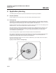
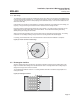
Installation, Operation & Maintenance Manual IP262/Z0, Rev. AB February 2012 MSL600 2. Application planning The following section discusses a few practical considerations when planning an installation. 2.1 Circular clarifiers Circular clarifiers are very common and can come with rotating or static bridges over them. 2.1.1 Rotating bridge If the transducer is mounted on a rotating bridge then it should be positioned on the leading edge of the bridge, see Figure (2).
Installation, Operation & Maintenance Manual MSL600 IP262/Z0, Rev. AB February 2012 2.1.2 Static bridge The transducer mounting arrangement is designed to lift out of the water if it is mounted on a fixed bridge when a moving scraper passes underneath (e.g. on a picket fence thickener). Ideally, the transducer should be mounted 1/3 to 2/3 of the way along from the outer (wall) edge of the settlement tank (i.e. 1/3 to 2/3 of the radius from the inside of the tank wall).
Installation, Operation & Maintenance Manual IP262/Z0, Rev. AB February 2012 MSL600 3. Installation The following section discusses installation considerations in more detail. 3.1 Preliminary checks Carefully unpack the MSL600 control unit, transducer, and mounting bracket arrangement from their packaging. Check that there is no visible damage to any of the packed parts, paying particular attention to the transducer and transducer cables, and the membrane keypad and display area on the MSL600.
Installation, Operation & Maintenance Manual MSL600 IP262/Z0, Rev. AB February 2012 With the bracket on the ground adjust the pivot tube up or down the main support tube until the distance between the angle bracket and midpoint of the transducer is dimension A. Adjust the clamping bracket up or down the main support tube to dimension B so it will be just clear of the final clamping position. If the clamp is higher than the pivot tube this will need to be removed and reassembled in reverse order (view X).
Installation, Operation & Maintenance Manual IP262/Z0, Rev.
Installation, Operation & Maintenance Manual IP262/Z0, Rev. AB February 2012 MSL600 3.4 Transducer connections The MSL600 is housed in an ABS enclosure rated to IP66. The lower section of the housing is for cable connections and the upper part has the LCD and keypad controls. It is not necessary, or advisable, to remove the lid of the upper part of the enclosure. There are no user serviceable parts inside.
Installation, Operation & Maintenance Manual IP262/Z0, Rev. AB February 2012 MSL600 The diagram below, Figure (7) shows the layout of external connection terminals of the MSL600 with the lower terminal housing cover removed. Table (A) gives a description of each. Note: When wiring of the unit is finished, ensure that the terminal housing cover is replaced the correct way up, i.e. with the bevelled edge uppermost otherwise the IP rating of the enclosure may be compromised.
Installation, Operation & Maintenance Manual MSL600 IP262/Z0, Rev. AB February 2012 3.6 Cable extension The transducer is connected using ALPHA XTRA-GUARD4 P/N45272. The standard cable length is 10 metres. This cable comprises of two twisted pairs with an overall screen and drain. The brown and red wires from the transducer should be connected to one twisted pair. The black and white wire from the transducer should be connected to the other twisted pair.
Installation, Operation & Maintenance Manual IP262/Z0, Rev. AB February 2012 MSL600 4. Programming The following sections introduce the main display and use of the keypad (MSL600 only) for programming the MSL600. Password protection to prevent unauthorized access is also discussed. 4.1 Display The display is a 240 x 128 dot matrix LCD module with full graphics capability and LED back light. The LCD is split into four parts, see Figure (8).
Installation, Operation & Maintenance Manual MSL600 IP262/Z0, Rev. AB February 2012 4.2 Contrast (viewing angle) control When the system is making measurements in normal mode the screen contrast or viewing angle can be adjusted. Whilst holding down the Esc key press either the n or p key Esc and - increases (darkens) the contrast and Esc and p decreases (lightens) the contrast. 4.
Installation, Operation & Maintenance Manual IP262/Z0, Rev. AB February 2012 MSL600 4.4 Security The HMI includes a password system which may be used to protect parameters from unauthorised changes and also to prevent the system from being switched between On and Off-line mode. The password is in the form of a 4-digit code (or PIN). When the user has entered the correct PIN then the password is said to be open (else closed). The PIN is a 4-digit code, value 0000 to 9999.
Installation, Operation & Maintenance Manual IP262/Z0, Rev. AB February 2012 MSL600 5. Quick start parameters The system leaves the factory with default values in all the parameters. These values, after installation, allow immediate operation without any further programming. However, it is recommended for best operation that the following parameters should be programmed. In order to get meaningful measurements from the MSL600 in the minimum time only the following parameters need to be adjusted. 5.
Installation, Operation & Maintenance Manual IP262/Z0, Rev. AB February 2012 MSL600 5.2 Determination of tank depth The ultimate blanket level measurement accuracy depends upon the accuracy of the value entered for the tank depth. It is always recommended that this be determined for every installation by the user using a measuring rod or similar.
Installation, Operation & Maintenance Manual MSL600 IP262/Z0, Rev. AB February 2012 5.4 mA current output parameters The operation of the current output is programmed by four parameters and is always controlled by the sludge blanket level. The current output parameters are found in SETUP – OUTPUT – CURRENT OUTPUT.
Installation, Operation & Maintenance Manual IP262/Z0, Rev. AB February 2012 MSL600 5.6 Relay parameters The MSL600 offers various options for operating its relays. There are 2 relays that are programmable to different modes, these modes are: • Alarm • Set point operation • De-sludge • On • Off • None • Fault • Slg Lev Limits (Sludge Level Limits) The mode of operation is selected through the SETUP – OUTPUT – RELAY – Relay Mode menu.
Installation, Operation & Maintenance Manual MSL600 IP262/Z0, Rev. AB February 2012 The transducer may take up to 1 hour to reach thermal equilibrium. Therefore, it may take some time to restore accurate blanket level readings. When the arm tilts out of the supernatant the MSL600 holds the last supernatant temperature reading from the transducer. When the transducer falls back into the supernatant the MSL600 starts to make measurements again.
Installation, Operation & Maintenance Manual IP262/Z0, Rev. AB February 2012 MSL600 6. Detailed operation The following sections go into programming the system in more detail. 6.1 The menu structure From the normal display, pressing the key will enter the menu system, see Figure (11). A full menu structure is shown in section 11. Main menu item Go On line ? INSTALLATION SETUP Tank Depth Xdr Tilt Time Tag No.
Installation, Operation & Maintenance Manual MSL600 IP262/Z0, Rev. AB February 2012 To move up and down the list, use the n and p arrows until the required menu item is highlighted, then use the key to enter that menu option. The presence of additional menu items off the screen is indicated by up and down arrows on the right hand side of the display. The next level of the menu is then displayed and the required option can again be selected as above. 6.
Installation, Operation & Maintenance Manual IP262/Z0, Rev. AB February 2012 MSL600 7. Application parameters The following section details each parameter. 7.1 Main menu parameters The following functions are available at the top level of the menu structure. Note: A full menu structure is shown in section 11. 7.1.1 Cancel password This is a dynamic parameter; it only appears when password has been opened.
Installation, Operation & Maintenance Manual IP262/Z0, Rev. AB February 2012 MSL600 7.2.4 Description – P240 This is a user defined alpha-numeric parameter. Any string up to 12 characters long may be entered using the keypad. This will usually be a description of the application. The following characters are allowed: !”#$%&’()*+,-./0123456789:;<=>?@ABCDEFGHIJKLMNOPQRSTUVWXYZ[\]^_ Parameter values: Default CLARIFIER1 Min - Max - 7.
Installation, Operation & Maintenance Manual IP262/Z0, Rev. AB February 2012 MSL600 7.3.3 Stop If - P252 Use this parameter to select if it is necessary to override the “Stop on” condition. The selectable options are: x Not used x Sludge Level The parameter defaults to none which means it is not used. Parameter values: Default None Min - Max - 7.3.4 Start Time - P253 This is the time of the day at which the first de-sludge operation starts. The time is programmed in hours and minutes.
Installation, Operation & Maintenance Manual IP262/Z0, Rev. AB February 2012 MSL600 7.4 Cleaning parameters The following parameter relates to the cleaning function. Note: A full menu structure is shown in section 11. 7.4.1 Start On - P260 Use this parameter to select how the cleaning cycle starts. The selectable options are: x AutoClean x Manual 5s x Off The default is “AutoClean”. 7.4.
Installation, Operation & Maintenance Manual IP262/Z0, Rev. AB February 2012 MSL600 7.5.3 Alarm Action - P402 This parameter is used to select the desired action which is taken by the mA output when the system is in an alarm condition. The allowed options are: x Go to 3.6mA x Go to 21mA x Hold (last reading) The default action is to go to 3.6mA. 7.5.4 0/4-20mA - P403 This parameter is used to select the desired range of the mA output from a list.
Installation, Operation & Maintenance Manual IP262/Z0, Rev. AB February 2012 MSL600 7.6 Relay parameters The following parameters are used to program the 2 available relays RL1 and RL2, which are controlled by the sludge blanket level. The mode of relay RL3 is fixed to fault indication. Note: A full menu structure is shown in section 11. P Mode On Point Off Point Min ON Max ON Min OFF RL1 410 411 412 413 414 415 RL2 420 421 422 423 424 425 Table (B): Relay Parameter numbers 7.6.
Installation, Operation & Maintenance Manual IP262/Z0, Rev. AB February 2012 MSL600 7.6.1.2 Fault mode (relay RL1 and RL2 parameters P560 to P570) There are several fault conditions which can be assigned to a relay. Fault conditions may be selected to be signalled by relay, current, both relay and current, or not at all. Messages describing active faults are automatically written to the lower HMI display. When a fault condition occurs, a relay configured in fault mode will de-energise.
Installation, Operation & Maintenance Manual MSL600 IP262/Z0, Rev. AB February 2012 7.6.2 Relay On and Off Points Relay On Point for RL1 (P411) and RL2 (P421) This is the sludge blanket level at which the Set Point mode relay turns on i.e. between 0.000 and 7.000m (0.00 to 23.00 ft). See also section 7.6.1.3 for related information. Relay OFF Point for RL1 (P412) and RL2 (P422) This is the sludge blanket level at which the Set Point mode relay turns off i.e. between 0.000 and 7.000m (0.00 to 23.00 ft).
Installation, Operation & Maintenance Manual IP262/Z0, Rev. AB February 2012 MSL600 7.7.2 Backlight On/Off - P575 The default for the display back light is "Auto". It can be switched to "Off" or "On". If set to Auto it is on when a key is pressed. The back light will automatically turn off after 5 minutes or if the internal temperature is too high and exceeds its programmed limits. It will turn on if the internal controller temperature is too low and is less than the programmed limit. 7.7.
Installation, Operation & Maintenance Manual IP262/Z0, Rev. AB February 2012 MSL600 7.8 Logging parameters Logged data can be downloaded and analysed via the RS232 port and Mobrey Measurement Log View Software (via a PC). For copies of this software, please contact Mobrey Measurement Sales. Note: A full menu structure is shown in section 11. 7.8.1 Log Interval - P590 The MSL600 can log the value (not the units) of the parameter that is shown on the middle of the HMI Display.
Installation, Operation & Maintenance Manual IP262/Z0, Rev. AB February 2012 7.9 MSL600 Engineering parameters The MSL600 blanket echo processing algorithm has been optimised for use on various types of municipal and industrial sludge. The user can select from either of two municipal sludge types depending on the application. The following parameters have been extensively tested and, once MUNICIPAL 1 or MUNICIPAL 2 sludge types have been chosen, the user should not need to adjust them.
Installation, Operation & Maintenance Manual IP262/Z0, Rev. AB February 2012 MSL600 7.9.2.2 Noise Alrm Lev – P622 The unit automatically monitors the background electronic noise floor as a % of display width, see parameter D834. If this level exceeds the Noise Alarm Lev value, programmed as a % of display width then an alarm can be indicated by allocating an output in P552, Noise Alarm. The default value is 25%. Parameter values: Default 25 Min 0 Max 100 7.9.2.
Installation, Operation & Maintenance Manual IP262/Z0, Rev. AB February 2012 MSL600 7.9.2.6 Lwr S-nat Temp – P626 This value is used for temperature compensation if the measured supernatant temperature is below this value. The lower temperature (P626) must always be less than the upper (P625). Valid entries are between –40 and +85°C (-40 to 185 deg F). The default is -5°C (25 deg F) Parameter values (metric) Default -5 Min -40 Parameter values (imperial) Max +85 Default 25 Min -40 Max 185 7.9.2.
Installation, Operation & Maintenance Manual IP262/Z0, Rev. AB February 2012 MSL600 7.9.3 Municipal 1 parameters P630 to P637 When the Municipal 1 algorithm is selected using parameter P620 (page 37), only the following specific parameters need to be adjusted. 7.9.3.1 Significance – P630 This parameter is used to select which echo in the echo profile that the Municipal 1 algorithm chooses as the most likely to correspond to the real sludge blanket level. The algorithm scans the echo profile for echoes.
Installation, Operation & Maintenance Manual IP262/Z0, Rev. AB February 2012 MSL600 7.9.3.5 Noise SD Mult – P635 The Municipal 1 algorithm scans the echo profile for echoes. Prior to sending pulses to the transducer, the noise floor is measured. It calculates the mean and standard deviation of fluctuations in the noise floor.
Installation, Operation & Maintenance Manual IP262/Z0, Rev. AB February 2012 MSL600 7.9.4 Municipal 2 parameter P640 Only one specific parameter, P640, needs to be adjusted when the Municipal 2 algorithm is selected. Industrial blankets are typically much denser and more substantial than municipal sludge found in a conventional wastewater plant. For this reason, the echo profile from an industrial sludge typically only displays one distinct echo. 7.9.4.
Installation, Operation & Maintenance Manual IP262/Z0, Rev. AB February 2012 7.10 MSL600 System parameters These parameters can be used to test the MSL600 hardware. Note: A full menu structure is shown in section 11. 7.10.1 AUTO CYCLE function The Auto Cycle or Self-Test function has the effect of automatically ramping up the sludge blanket level value between its minimum and maximum values so as to exercise the current output and relays without the actual blanket level changing.
Installation, Operation & Maintenance Manual MSL600 IP262/Z0, Rev. AB February 2012 7.10.5 COMMS parameters P710 to P716 These parameters are used for serial RS232 communications. 7.10.5.1 Address - P710 Poll Address. The default value of this parameter should not be changed. The parameter is included in the menu system for future software updates. Default = 0 7.10.5.2 Interface - P711 The type of serial interface. The default value of this parameter should not be changed.
Installation, Operation & Maintenance Manual IP262/Z0, Rev. AB February 2012 MSL600 7.10.6.4 Date format - P734 The format for the date can be chosen from a list: x yy/mm/dd x dd/mm/yy (Default metric) x mm/dd/yy (Default imperial) 7.10.6.5 Keypad Sound - P735 Each time a key is pressed, a beep sounds as confirmation of the key being pressed. This audio feedback can be turned off. The default is on. 7.10.6.6 Language - P737 The HMI default language is English.
Installation, Operation & Maintenance Manual MSL600 7.11 IP262/Z0, Rev. AB February 2012 Readings and diagnostics parameters The user can not alter the value of readings or diagnostics parameters within the MONITOR menu. Note: A full menu structure is shown in section 11. 7.11.1 Readings parameters D800 to D834 7.11.1.1 Sludge Level - D800 The main process variable, the sludge blanket level in metres (feet – imperial).
Installation, Operation & Maintenance Manual IP262/Z0, Rev. AB February 2012 MSL600 7.11.1.9 Xdr Tilt Time - D833 A diagnostic parameter indicating the time for which the transducer has been out of the water in min:secs. 7.11.1.10 Noise Level - D834 A diagnostic parameter indicating the noise level in the tank as a % of full screen. 7.11.2 Diagnostics parameters D835 to D852 7.11.2.
Installation, Operation & Maintenance Manual MSL600 IP262/Z0, Rev. AB February 2012 7.11.2.10 Speed of Sound - D850 View this parameter to see the temperature compensated speed of sound in the supernatant which the MSL600 is using in its calculation of sludge blanket level in m/s (imperial – ft/s). 7.11.2.11 Max Xdr Temp - D851 View this parameter to see the maximum temperature in °C (imperial – degrees F) which has been experienced by the transducer.
Installation, Operation & Maintenance Manual IP262/Z0, Rev. AB February 2012 MSL600 8. Technical reference 8.1 Transmit pulse and echo processing The transducer and it’s transmit and receive circuitry is optimized to work at 1.0MHz. Some sludge blankets are indistinct. The algorithm has been optimised to average out and ignore unwanted signals produced by particles in the supernatant, whilst detecting and measuring the wanted signals from the sludge blanket.
Installation, Operation & Maintenance Manual IP262/Z0, Rev. AB February 2012 MSL600 11. Programming chart Main Menu Option Sub-menu Level 1 Sub-menu Level 2 Cancel Password (only seen if the password is active) Go Offline ? INSTALLATION SETUP DUTY(Mode) Sub-menu Level 3 DESLUDGE CLEANING OUTPUT CURRENT OUTPUT RELAY RELAY 1 RELAY 2 RELAY 3 ALARM FAULT DISPLAY Clear Trend Clear Profile LOGGING Parameter Title Tank Depth Xdr Tilt Time Tag No.
Installation, Operation & Maintenance Manual IP262/Z0, Rev. AB February 2012 MSL600 Programming chart continued… ENGINEERING CONFIG ALGORITHM COMMON MUNICIPAL 1 SYSTEM TEST MUNICIPAL 2 AUTO-CYCLE DISPLAY CURRENT OUTPUT LOAD DEFAULTS COMMS RADIO SETTINGS FIXED Page 51 Alg. Select Ave.
Installation, Operation & Maintenance Manual IP262/Z0, Rev.
Installation, Operation & Maintenance Manual IP262/Z0, Rev. AB February 2012 MSL600 12. Specification 12.1 MSL600 Model No. MSL600 Operating principle Ultrasonic sonar Range 7.0m (23 feet) Dead band 0.3m (1 foot) Accuracy +/-35mm (+/- 1.
Installation, Operation & Maintenance Manual IP262/Z0, Rev. AB February 2012 MSL600 Weight Enclosure & compressor housing Transducer & mounting bracket Approvals 7.0 Kg / 15.4 lbs 12.0 Kg / 26.4 lbs CE, LVD, EMC Max Altitude 2000m Max Humidity 95% RH Pollution Degree 2-1EC664 Additional specification notes: Programming menu using Mobrey HMI. Sludge blanket level from bottom of the clarifier. Icon enunciators display the relay status.
Installation, Operation & Maintenance Manual IP262/Z0, Rev. AB February 2012 13.
Installation, Operation & Maintenance Manual MSL600 IP262/Z0, Rev.
Installation, Operation & Maintenance Manual IP262/Z0, Rev. AB February 2012 MSL600 14. MSL603 transducer cable extension Parts required: ITT Cannon TNM connectors (Cannon part no.) [R.S. stock no.
Installation, Operation & Maintenance Manual MSL600 IP262/Z0, Rev.
Installation, Operation & Maintenance Manual IP262/Z0, Rev.
Installation, Operation & Maintenance Manual IP262/Z0, Rev. AB February 2012 MSL600 The Emerson logo is a trade mark and service mark of Emerson Electric Co. Rosemount is a registered trademark of Rosemount Inc. Mobrey is a registered trademark of Mobrey Ltd. All other marks are the property of their respective owners. We reserve the right to modify or improve the designs or specifications of product and services at any time without notice. © 2012 Mobrey Ltd. All rights reserved.