Instruction Manual PN 51-381/rev.
ESSENTIAL INSTRUCTIONS READ THIS PAGE BEFORE PROCEEDING! Rosemount Analytical designs, manufactures, and tests its products to meet many national and international standards. Because these instruments are sophisticated technical products, you must properly install, use, and maintain them to ensure they continue to operate within their normal specifications.
MODEL 381 pH/ORP TABLE OF CONTENTS MODEL 381 pH/ORP SENSOR TABLE OF CONTENTS Section 1.0 1.1 1.2 1.3 Title DESCRIPTION AND SPECIFICATIONS........................................................... Features and Applications................................................................................. Sensor Specifications........................................................................................ Ordering Information ..........................................................................
MODEL 381 pH/ORP TABLE OF CONTENTS MODEL 381 pH/ORP SENSOR LIST OF FIGURES Figure No. 1-1 1-2 2-1 2-2 2-3 2-4 2-5 2-6 2-7 2-8 2-9 4-1 4-2 Title Dimensional Drawing ........................................................................................ Mounting Drawing ............................................................................................. Model 381 Sensor Component Locator Diagram.............................................. Submersion Installation Diagram ........................
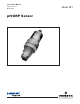
MODEL 381 pH/ORP SECTION 1.0 DESCRIPTION AND SPECIFICATIONS SECTION 1.0 DESCRIPTION AND SPECIFICATIONS • MOLDED POLYETHERSULFONE (PES) BODY provides compatibility with a variety of processes. • MODULAR DESIGN facilitates maintenance by eliminating terminal and mounting brackets and extraneous hardware. • INTEGRAL PREAMPLIFIER provides reliable signal transmission.
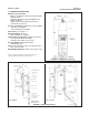
MODEL 381 pH/ORP SECTION 1.0 DESCRIPTION AND SPECIFICATIONS 1.2 SENSOR SPECIFICATIONS Materials of Construction: Body, Cover and Flow Cell: Polyethersulfone (PES). O-Rings: Viton2. Measuring Electrode: Glass (and platinum for Model 381 ORP). Liquid Junction: Kynar3/wood (Code 20) or Kynar/ceramic (Code 21). Process Connections: Submersion: 3/4 inch MNPT. Insertion: 2 inch MNPT. Flow Through:3/4 inch MNPT. Dimensions: (see Figure 1-1).
MODEL 381 pH/ORP SECTION 1.0 DESCRIPTION AND SPECIFICATIONS 1.3 ORDERING INFORMATION Model pH/ORP Sensor is housed in a PES body suitable for insertion, submersion or flow through installation. The sensor includes an integral preamplifier, measuring electrode, double junction gel-filled reference cell, automatic temperature compensation for pH, and a choice of two cable lengths of either 15 ft. or 50 ft. (4.5 or 15.2 m).
4 This page left blank intentionally.
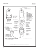
MODEL 381pH/ORP SECTION 2.0 INSTALLATION SECTION 2.0 INSTALLATION 2.1 INSTALLATION. Prepare the sensor for installation as follows (see Figure 2-1): IMPORTANT! 12. While holding the sensor in an up side down position (see Figure 2-1), remove the 1/4 inch plug from the electrode tip end of the sensor. 1. Remove the cover from the body by grasping the body and rotating the cover 1/4 turn counterclockwise. 2. When the cover breaks loose from the body, pull the cover straight out. 13.
MODEL 381pH/ORP SECTION 2.0 INSTALLATION FIGURE 2-1.
MODEL 381pH/ORP SECTION 2.0 INSTALLATION 2.3 INSERTION INSTALLATION (Code 00). To install the sensor in the side of a tank, in a pipeline, or in a pipe “tee”, proceed as follows (see Figure 2-3): NOTE Electrode shroud and coupling nut should be hand tightened only. Do not use a wrench. When tightening process or sample line connectors to the flow cell do not use a pipe wrench on the flow cell. Severe damage may result. CAUTION Sensor must be installed within 80° of the vertical plane (see Figure 2-3).
MODEL 381pH/ORP SECTION 2.0 INSTALLATION FIGURE 2-2. Submersion Installation Diagram FIGURE 2-3.
MODEL 381pH/ORP SECTION 2.0 INSTALLATION FIGURE 2-4. Flow Through Installation Diagram (Code 03 or 04) FIGURE 2-5.
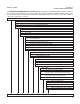
MODEL 381pH/ORP SECTION 2.0 INSTALLATION PRESSURE DROP AND RECOMMENDED FLOW RATES- FLOW POWERED CLEANER (CODE 04) kPa PSIG 240 20 PRESSURE DROP 220 POSSIBLE ELECTRODE DAMAGE ABOVE THE THIS POINT 200 15 180 160 10 RECOMMENDED OPERATING RANGER 140 120 100 5 INEFFECTIVE CLEANING BELOW THIS POINT 1 2 5 3 10 4 15 5 20 6 7 8 gpm @ 60° 25 30 liters/min FLOW RATE FIGURE 2-6.
MODEL 381pH/ORP SECTION 2.0 INSTALLATION WHEN INCH AND METRIC DIMS ARE GIVEN MILLIMETER INCH DWG. NO. 40038105 REV. L FIGURE 2-7.
MODEL 381pH/ORP SECTION 2.0 INSTALLATION WHEN INCH AND METRIC DIMS ARE GIVEN MILLIMETER INCH DWG. NO. 40038103 FIGURE 2-8. Remote Junction Box with Internal Preamp 12 REV.
MODEL 381pH/ORP SECTION 2.0 INSTALLATION WHEN INCH AND METRIC DIMS ARE GIVEN MILLIMETER INCH DWG. NO. REV. 40038116 I DWG. NO. 40038115 REV. K FIGURE 2-9. Wiring with Weatherproof or Div.
MODEL 381pH/ORP 2.7 START-UP AND CALIBRATION 2.8 MODEL 381 pH and pHE 2.8.1 SENSOR PREPARATION. Shake down the sensor to remove any air bubbles that may be present at the tip of the pH glass bulb. In most cases, the pH sensor can simply be installed as shipped and readings with an accuracy of ± 0.6 pH may be obtained. To obtain greater accuracy or to verify proper operation, the sensor must be calibrated as a loop with its compatible analyzer or transmitter.
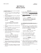
MODEL 381pH/ORP SECTION 3.0 MAINTENANCE SECTION 3.0 MAINTENANCE 3.1 GENERAL. This section provides instructions for performing periodic maintenance and for determining the cause of a malfunction (troubleshooting). 3.2 PERIODIC MAINTENANCE. The following periodic maintenance is based on operation in a water sample. Determine the schedule for the operation being maintained from past experience, or by analyzing data gathered since initial installation of the sensor. 3.2.1 Monthly.
MODEL 381pH/ORP SECTION 3.0 MAINTENANCE 3.3 MODEL 381 Slowly and carefully add 56.2 milliliters of concentrated sulfuric acid. Add sufficient water to bring the total solution volume up to 1000 ml. This standard ORP solution, although not as simple to prepare as the quinhydrone recipe, is much more stable, and will maintain its millivolt value for approximately one year when stored in glass containers.
MODEL 381pH/ORP SECTION 3.0 MAINTENANCE TABLE 3-1. Troubleshooting Trouble Probable Cause Reference electrolyte depleted. Replace reference electrolyte as instructed in Section 3.2.2. Defective preamplifier. Check preamplifier as instructed in Section 3.4 and replace preamplifier if defective. T.C. element shorted. Check T.C. element as instructed in Section 3.5, and replace body if defective. Electrode not in solution or sample stream is not full.
MODEL 381pH/ORP 3.4 PREAMPLIFIER TROUBLESHOOTING. To determine if the preamplifier is operable, proceed as follows: 1. 2. 3. Remove the sensor from process. Remove the cover from the body by grasping the body and rotating the cover 1/4 turn in the counter-clockwise direction. When the cover breaks loose from the body, pull straight out on the cover to expose the components attached to the body and disconnect the BNC connector from the preamplifier, leaving the cable connected.
MODEL 381pH/ORP SECTION 3.0 MAINTENANCE TABLE 3-4.
20 This page left blank intentionally.
MODEL 381pH/ORP SECTION 4.0 ULTRASONIC CLEANER SECTION 4.0 ULTRASONIC CLEANER 4.1 ULTRASONIC CLEANER (P/N 22727-00). This accessory provides an ultrasonic cleaner and mounting hardware for either continuous or inter-mittent cleaning of the measuring electrode and liquid junction on the Model 381. The information in the following paragraph is supplemental to the information in Sections 1.0 thru 3.0. 4.2 SPECIFICATIONS. The ultrasonic cleaner operates on either 115 Vac or 230 Vac, 50/60 Hz.
MODEL 381pH/ORP 4.4 Operation (continued) NOTE When the ultrasonic cleaner is used on some slurry applications (such as car- bonates and phosphates), continuous ultrasonic cleaning is not recommended as this may tend to compact the solids of the slurry on the electrode into a hard, cement like coating. Instead, it is recommended that a shock-type treatment be applied (i.e., for every three hours of operation, employ 30 minutes of ultrasonic cleaning).
MODEL 381pH/ORP SECTION 4.0 ULTRASONIC CLEANER WHEN INCH AND METRIC DIMS ARE GIVEN MILLIMETER INCH DWG. NO. 40038156 REV. F FIGURE 4-1.
MODEL 381pH/ORP SECTION 4.0 ULTRASONIC CLEANER WHEN INCH AND METRIC DIMS ARE GIVEN MILLIMETER INCH DWG. NO. 40037505 FIGURE 4-2. Dimensional and Component Locator Ultrasonic Generator 24 REV.
MODEL 381 SECTION 5.0 RETURN OF MATERIAL SECTION 5.0 RETURN OF MATERIAL 5.1 GENERAL. To expedite the repair and return of instruments, proper communication between the customer and the factory is important. The “Return of Materials Request” form is provided for you to copy and use in case the situation arises. The accuracy and completeness of this form will affect the processing time of your materials. Call 1 (949) 757-8500 for a Return Materials Authorization (RMA) number. 5. Rosemount Analytical Inc.
RETURN OF MATERIALS REQUEST C U S T O M E R N O T I C E T O FROM: •IMPORTANT! This form must be completed to ensure expedient factory service.
WARRANTY Goods and part(s) (excluding consumables) manufactured by Seller are warranted to be free from defects in workmanship and material under normal use and service for a period of twelve (12) months from the date of shipment by Seller. Consumables, pH electrodes, membranes, liquid junctions, electrolyte, O-rings, etc. are warranted to be free from defects in workmanship and material under normal use and service for a period of ninety (90) days from date of shipment by Seller.
The right people, the right answers, right now. ON-LINE ORDERING NOW AVAILABLE ON OUR WEB SITE http://www.raihome.com Specifications subject to change without notice. 8 Credit Cards for U.S. Purchases Only. Emerson Process Management 2400 Barranca Parkway Irvine, CA 92606 USA Tel: (949) 757-8500 Fax: (949) 474-7250 http://www.raihome.com © Rosemount Analytical Inc.