
- Emerson Electric Co. Whiteboard Accessories User Manual


INSTALLATION AND SETUP 2-57
MON2000
JULY 2010 2350A Modem Installation
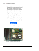
(c) Plug one end of the modem extension
cable (P/N 3-2350-075) into J1 of the
modem assembly. The in-line jack on the
remaining end of the modem extension
cable attaches to the lower left inside
wall of the card cage shield (after the
CPU assembly is reinstalled and all
cables reconnected to the System
Interface board). No software setup is
required for this board.
7. To use an existing Modem (1414):
(a) For operation with the 2350A CPU, set
the Standard 1414 Modem jumpers per
the following table:
(b) On the 2350A WinSystems CPU, set J21,
pin 13-14.
Table 2-6 1414 (Standard) Modem Jumper Settings
Jumper Pin
J4/J5 Open
J6 3-5, 4-6
J7 7-8
J9 Open