Reference Manual MHM-97408, Rev 15 January 2015 CSI 9420 Wireless Vibration Transmitter Reference Manual
Read this manual before working with the product. For personal and system safety, and for optimum product performance, make sure to thoroughly understand the contents before installing, using, or maintaining this product. If you need product support, contact: Global Service Center (GSC) Phone: 1-800-833-8314 1-877-812-4036 Email: mhm.custserv@emerson.com Web: http://www.assetweb.com/mhm and select Product Support World Wide Customer Service Phone: 1-888-367-3774 (Option 2 CSI) Email: wwcs.
Copyright © 2015 by Emerson Process Management. All rights reserved. No part of this publication may be reproduced, transmitted, transcribed, stored in a retrieval system, or translated into any language in any form by any means without the written permission of Emerson Process Management. Disclaimer This manual is provided for informational purposes.
Contents Contents Chapter 1 Introduction ...................................................................................................................1 1.1 1.2 1.3 1.4 Chapter 2 Configuration .................................................................................................................7 2.1 2.2 2.3 2.4 Chapter 3 Safety messages .......................................................................................................................... 1 Overview ...............
Contents Chapter 4 Operation and maintenance ......................................................................................... 87 4.1 4.2 Chapter 5 Velocity, PeakVue, and temperature ............................................................................ 91 5.1 5.2 5.3 Chapter 6 Verify status and operation ........................................................................................................ 87 Power module maintenance ....................................................
Introduction 1 Introduction Topics covered in this chapter: • • • • 1.1 Safety messages Overview Considerations Return of materials Safety messages Instructions in this manual may require special precautions to ensure the safety of the personnel performing the operations. Refer to the following safety messages before performing an operation preceded by the warning symbol. WARNING! Failure to follow these installation guidelines can result in death or serious injury.
Introduction 1.2 Overview The manual This Reference Manual applies to the 2.4 GHz WirelessHART version of the CSI 9420 for use with the Smart Power Module unless otherwise specified. It is optimized for use with the most recent device and software revisions (AMS Suite: Machinery Health Manager v5.61 and AMS Suite: Intelligent Device Manager v12.5). Use this manual to install, operate, and maintain the CSI 9420 Wireless Vibration Transmitter.
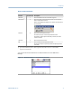
Introduction Device revision information Revision Current level Description Universal 7 This is the HART version the transmitter supports. Field device(1) 4 This is the major revision of the transmitter and corresponds with a major interface release. When using AMS Device Manager, this revision can be found on the screen title. Software 6 This is the current software version. The software may be occasionally modified to refine functionality.
Introduction Figure 1-2: Revision numbers in AMS Device Manager 4 MHM-97408, Rev 15
Introduction 1.3 Considerations General Electrical vibration sensors, such as accelerometers, produce low-level signals proportional to their sensed vibration. With simple HART configuration, the transmitter converts the low-level sensor signal to a wireless-enabled signal. Commissioning The transmitter can be commissioned before or after installation. You can commission it on the bench before installation to ensure proper operation and to be familiar with its functions.
Introduction Environmental The transmitter operates within specifications for ambient temperatures between –40°F and 185°F (–40°C and 85°C). Verify that the operating environment of the transmitter is consistent with the appropriate hazardous location certifications. 1.4 Return of materials You may need to ship the CSI 9420 to an Emerson Product Service Center for return or maintenance.
Configuration 2 Configuration Topics covered in this chapter: • • • • 2.1 Configuration overview Configuration with a Field Communicator Configuration with AMS Device Manager Configuration with AMS Machinery Manager Configuration overview You can configure the CSI 9420 either prior to installation or after the device is installed at the measurement location. You do not need to physically install or connect to the transmitter to complete the configuration.
Configuration 6. Specify the units (English, metric, or SI) that will be used for each parameter. By default, units are set to English, unless the device is shipped to Japan. 7. Specify which measurements (velocity, temperature, etc.) correspond to the process variables PV, SV, TV, and QV. By default, PV is the Overall Velocity on sensor 1, SV is the PeakVue measurement on sensor 1, TV is the sensor 1 bias voltage, and QV is the supply voltage. 8. Specify alert levels.
Configuration 2.1.1 Connect to a wired HART interface Unless the CSI 9420 is purchased pre-configured from the factory, you must connect it to a wired HART interface. This is to define device credentials that allow the device to communicate on your wireless network. You can also define other device configurations such as sensor type and alert thresholds at this time. Notes • Use the wired HART interface only for configuration.
Configuration Figure 2-2: Field Communicator and power module connection 3. Configure using a Field Communicator, AMS Device Manager, or any HART-enabled host. Press Send to send configuration changes to the transmitter. The CSI 9420 enters “HART Listen” mode for communication on the wired interface. HART Listen is displayed on the optional LCD, if it is installed.
Configuration 4. When configuration is complete over the wired HART interface, disconnect the transmitter from the communication wires to re-establish wireless communication. This may take several minutes. 2.1.2 Set the wireless network configuration This enables the transmitter to communicate with the Smart Wireless Gateway and with other systems. This is the wireless equivalent of connecting wires from a transmitter to a control system input. Procedure 1.
Configuration 2.1.3 Configuration options The CSI 9420 configuration options control the following operations: • How measurement results are reported and how often are they reported • The number and type of sensors installed • How and when alerts are generated Table 2-1 shows the default device configuration. You can change these configurations from AMS Device Manager or from a Field Communicator.
Configuration 2.1.4 Sensor configuration The CSI 9420 can be installed with two accelerometers, or with one accelerometer with an embedded temperature sensor. Table 2-2 shows the possible sensor configurations and variable mappings.
Configuration 2.1.5 Measurement parameter units Table 2-3 shows the measurement parameters and available units that can be configured for each parameter. Table 2-3: Measurement parameter units Parameter Units mm/s RMS Velocity (Overall 1, Overall 2) in/s RMS m/s2 PeakVue maximum value (PeakVue 1, PeakVue 2) g’s °C Temperature (Temperature 1, Ambient) 2.1.
Configuration Table 2-4: Default alert thresholds for vibration (continued) Advise Alert limits Default value Sensor 65°C temperature 149°F Bias Ambient temperature Supply voltage Report notification Default value Default value – – – – <6.0 V No <5.7 V Yes Yes 185°F Above: >3V – – Report notification 85°C Yes 167°F – Failed Report notification 75°C Yes – (sensor 1, 2) Maintenance Yes* Below: <2V Above: 85°C (185°F)* Yes* Below: -40°C (-40°F)* <5.
Configuration Table 2-6: Default levels for configurable device alerts Parameter Advisory Maintenance Failed Level Enabled Level Enabled Level Enabled Accelerometer Bias N/A N/A N/A N/A < 2 V or > 3 V Yes Supply Voltage < 6.0 V No < 5.7 V Yes < 5.3 V Yes Notes 2.1.7 • The supply voltage measurement is made under load conditions. The supply voltage may read differently with the CSI 9420 versus other Emerson transmitters or multimeters.
Configuration 2.1.9 Minimize power consumption The primary way to minimize power consumption is to reduce the publish rate. Two other configuration settings that affect power consumption are: • LCD (Liquid Crystal Display) • PowerSave mode LCD Disable the LCD after installation is complete if it is not required during normal operation. It is neither necessary nor sufficient to physically remove the LCD; it must be disabled through configuration in order to save power.
Configuration Valid settings for the PowerSave Skip Multiplier range from 1X to 24X. In order to extend power module life, it should only be combined with a long update rate such as 60 minutes (54 minutes may be optimal for older versions of the CSI 9420). When this value is set to 1X, the CSI 9420 acquires a new reading at the update rate. A PowerSave Skip Multiplier of 2X combined with a 60-minute update rate results in a new acquisition every 120 minutes (every two hours).
Configuration 2.1.11 Remove the power module The CSI 9420 device is powered whenever the power module is installed. To avoid depleting the power module, remove it when the device is not in use. After you have configured the sensors and network, disconnect the communication leads, remove the power module (if the device is not already installed), and replace the transmitter cover. You should insert the power module only when you are ready to commission the device. 2.
Configuration Figure 2-4: Field Communicator menu tree for CSI 9420, one accelerometer: 1 of 4 20 MHM-97408, Rev 15
Configuration Figure 2-5: Field Communicator menu tree for CSI 9420, one accelerometer: 2 of 4 MHM-97408, Rev 15 21
Configuration Figure 2-6: Field Communicator menu tree for CSI 9420, one accelerometer: 3 of 4 22 MHM-97408, Rev 15
Configuration Figure 2-7: Field Communicator menu tree for CSI 9420, one accelerometer: 4 of 4 MHM-97408, Rev 15 23
Configuration Figure 2-8: Field Communicator menu tree for CSI 9420, one accelerometer with temperature: 1 of 4 24 MHM-97408, Rev 15
Configuration Figure 2-9: Field Communicator menu tree for CSI 9420, one accelerometer with temperature: 2 of 4 MHM-97408, Rev 15 25
Configuration Figure 2-10: Field Communicator menu tree for CSI 9420, one accelerometer with temperature: 3 of 4 26 MHM-97408, Rev 15
Configuration Figure 2-11: Field Communicator menu tree for CSI 9420, one accelerometer with temperature: 4 of 4 MHM-97408, Rev 15 27
Configuration Figure 2-12: Field Communicator menu tree for CSI 9420, two accelerometers: 1 of 4 28 MHM-97408, Rev 15
Configuration Figure 2-13: Field Communicator menu tree for CSI 9420, two accelerometers: 2 of 4 MHM-97408, Rev 15 29
Configuration Figure 2-14: Field Communicator menu tree for CSI 9420, two accelerometers: 3 of 4 30 MHM-97408, Rev 15
Configuration Figure 2-15: Field Communicator menu tree for CSI 9420, two accelerometers: 4 of 4 MHM-97408, Rev 15 31
Configuration 2.2.1 Field Communicator fast key sequences The following fast key sequences assume that you are using a Rev 4 DD. Press Send to save the changes to the device.
Configuration Table 2-8: CSI 9420 common fast key sequences (continued) MHM-97408, Rev 15 Function Key sequence Menu items Power options 2, 2, 3, 2 (Manual Setup) Power Source MHM Access Control 2, 2, 3, 6 (Manual Setup) MHM Access Control Supply power to sensor 2, 1, 5 (Guided Setup) Sensor Power Enable Configure variable mapping 2, 1, 2 (Guided Setup) Configure Variable Mapping Device reset 3, 6, 5 Device Reset Restore Factory Default Settings 33
Configuration 2.3 Configuration with AMS Device Manager 2.3.1 Configure wireless network credentials in AMS Device Manager Prerequisites Before performing operations in AMS Device Manager, first scan the CSI 9420 with a wired HART modem. Right-click the HART Modem icon Devices. in Device Explorer and select Scan All Note Configuring the wireless network is only applicable using a wired HART modem and cannot be done using WirelessHART devices. Procedure 1.
Configuration 2.3.2 Right-click menu The right-click menu of the CSI 9420 device in AMS Device Manager provides a quick link to the Configure, Compare, Service Tools, and Overview windows, as well as to other context menus available for the device. This document only discusses the Overview, Configure, and Service Tools windows; for more information on the other context menus, refer to AMS Device Manager Books Online.
Configuration Overview Figure 2-17: Overview window The Overview window provides a glimpse of the status of the CSI 9420, including the primary purpose variables associated with it.
Configuration Device Information From the Overview window, click Device Information to display relevant device information. Figure 2-18: Device Information window Click the Identification tab to display the device tag, long tag, device type, serial number, identifier, and description. Click the Revisions tab to display the universal, field device, software, hardware, and DD revision numbers.
Configuration Configure Sensors From the Overview window, click Configure Sensors to display installed sensors and current sensor configurations. Figure 2-19: Sensor Configuration window Click the Select Sensor Configuration drop-down to select a sensor configuration to apply to the installed sensors.
Configuration Join Device to Network From the Overview window, click Join Device to Network to enter network identifiers and join keys that will enable the transmitter to join a wireless network.
Configuration Acquire New Measurement From the Overview window, click Acquire New Measurement to display measurement statistics for Velocity, PeakVue, bias, and sensor temperature for installed sensors. This also displays supply voltage and ambient temperature information for the transmitter.
Configuration Configure Figure 2-22: Configure window The Configure window lets you configure device settings. Important To be able to edit configuration settings, select Current in the Time drop-down menu at the bottom of the screen. Guided Setup Guided Setup lets you configure device settings in a guided step-by-step process. Click Configure Sensors to display or configure installed sensors.
Configuration Note Sensor Power Enable is only available when the device is connected to AMS Device Manager using a USB or serial HART modem and when the device is connected to a Field Communicator. This feature is not available when the device is connected to AMS Device Manager using a WirelessHART connection. Click Join Device to Network to enter network identifiers and join keys that will enable the transmitter to join a wireless network.
Configuration Click Configure Update Rate to set how often the device acquires and reports new measurements (update rate) and to specify the number of times the transmitter skips data acquisitions between updates to the gateway (PowerSave Skip Multiplier). Click Default Burst Configuration to reset the burst configuration to default values. Click Refresh Effective Acquisition Rate to refresh the value in the Effective Acquisition Rate field. Click the Sensor tab to display current sensor configurations.
Configuration Click the General Settings tab to display or edit general transmitter settings. Figure 2-25: General Settings tab Click the LCD Mode drop-down to enable or disable the LCD, or to set it to troubleshooting mode. Click the Power Source drop-down to select the transmitter power source. Select the units for measurement variables from the Overall Velocity, PeakVue, and Temperature drop-down menus.
Configuration Click the Mapping tab to specify which measurements are reported as the Primary, Secondary, Third, and Fourth variables.
Configuration Click the Device Information tab to display the device tag, long tag, device type, serial number, device identifier, and description, and to display the universal, field device, software, hardware, and DD revision numbers.
Configuration Click the License tab to display installed licensable features such as the Advanced Diagnostics application. Figure 2-28: License tab Click Configure License to configure/change installed licenses.
Configuration Alert Setup Alert Setup lets you configure the upper and lower range values and alarm limits for Overall Velocity, PeakVue, Bias, Sensor Temperature, Ambient Temperature, and Supply Voltage. Figure 2-29: Alert Setup Click the corresponding sensor/device variable tab and select the Report Advisory, Report Maintenance, or Report Failure check boxes to generate alarms when actual measured values exceed the thresholds specified. When these check boxes are not selected, no alarm is reported.
Configuration Service Tools Figure 2-30: Service Tools window The Service Tools window displays alert conditions. These include hardware and software malfunctions or parameters with values beyond specifications. Alerts Click Alerts to display active alerts for the device.
Configuration Variables Click Variables to display graphical gauges of sensor and device variables. Figure 2-31: Variables Click the Mapped Variables tab to display graphical gauges of variables and their mappings. Click the Sensor Variables tab to display graphical gauges of the variables for each connected sensor. Click the Device Variables tab to display graphical gauges of ambient temperature and supply voltage variables.
Configuration Trends Click Trends to display hour-long trends for each of the four measurement variables (PV, SV, TV, and QV). Figure 2-32: Trends Note The trend plots begin when Trends is selected, and continue to build as long as this remains selected.
Configuration Spectra Click Spectra to display spectral and analysis parameter data and to configure spectral data acquisition settings. You can import spectral data to AMS Machinery Manager for further analysis. Note You must have the Advanced Diagnostics application license to view this feature. For more information on the Advanced Diagnostics application, see Section 2.4.1. Figure 2-33: Spectra The Fmax settings define the default frequency range of the thumbnail spectra for Velocity and PeakVue.
Configuration Click Velocity Spectrum x and PeakVue Spectrum x to display spectral plots of the latest acquired data for Velocity and PeakVue for connected sensors.
Configuration Figure 2-35: PeakVue spectrum 54 MHM-97408, Rev 15
Configuration Click the Energy Bands tab to display calculated energy band values.
Configuration Communications Click Communications to display network join status information. Figure 2-37: Communications Click the Join Mode drop-down to select when the transmitter attempts to join a network.
Configuration Maintenance Click Maintenance to manage the device maintenance and log settings. Figure 2-38: Maintenance Click Routine Maintenance tab > Advertise to New Wireless Devices to enable the gateway to search for new wireless devices on the network. This helps new devices join the network faster. Click the Event History tab to display transmitter events such as measurements, HART transmissions, and wake actions. Click the Log Configuration tab to configure event logging options.
Configuration 2.4 Configuration with AMS Machinery Manager AMS Machinery Manager can change the data acquisition settings for CSI 9420 devices. If the device is not commissioned in a HART DCS host (DeltaV or Ovation), you can allow AMS Machinery Manager to configure settings to provide easier access. You need to configure MHM Access Control in AMS Device Manager or in a Field Communicator to allow AMS Machinery Manager to make configuration changes to the CSI 9420.
Configuration Other configurable parameters for the energy band include: • Effective Fmax for the thumbnail spectrum — For the velocity thumbnail spectrum, AMS Machinery Manager uses 100% as the default Fmax. • True Fmax for PeakVue — This allows the monitoring of a slower machine with PeakVue. Choosing 1000 Hz Fmax uses about 1.6 seconds of data to produce a 1000 Hz analytical spectrum. Choosing 500 Hz Fmax uses about 3.2 seconds of data to produce a 500 Hz analytical spectrum.
Configuration When using a power module, the maximum recommended time-based acquisition rates are: • Thumbnail spectrum — Once per day • High-resolution spectrum — Once every two weeks • Waveform — Once per month On-demand data collection is not expected to have a significant impact on power module life. If you are using a power module, keep in mind that even on-demand acquisitions can have an adverse effect on the power module life if you request data, especially highresolution data, too frequently.
Configuration Figure 2-39: Verify device revision Note If you have an older device revision, a factory upgrade may be possible in some cases. Contact Product Support for more information. 3. Right-click the CSI 9420 device and select Configure. 4. From the Configure window, select Current from the Time drop-down menu. 5. Click Manual Setup > License tab > Configure License. 6. Select Yes to enable the Advanced Diagnostics application. This displays the serial number and request number.
Configuration Enable Advanced Diagnostics application (alternative) If your CSI 9420 is not installed on a wireless network, you can perform the upgrade using either a HART modem or a 375 or 475 Field Communicator. WARNING! The hazardous area rating available with the CSI 9420 does not permit either of the following operations to be performed in a hazardous area.
Configuration To make changes to a CSI 9420, AMS Device Manager settings must allow AMS Machinery Manager to make changes. Note In some cases, if the gateway device is connected to a HART host such as DeltaV, any changes made using the AMS Machinery Manager software will be rejected. In such cases, contact your DeltaV administrator or an instrument technician who is authorized to make the required configuration changes.
Configuration • You want to limit how often you collect and store data. Consider the following example in which a CSI 9420 is configured for a 60 minute update rate and to request the PeakVue spectrum whenever the PeakVue value exceeds 10 g's. If the measurement stays above 10 g's for an extended period of time, AMS Machinery Manager, without a publishing policy, would request a new spectrum with every measurement or once every hour.
Configuration How to apply a publishing policy You can apply a publishing policy globally to a Data Import Server or individually to each gateway device. 2.4.4 • Apply a publishing policy to a Data Import Server to affect each gateway monitored by that server. • Apply a publishing policy to one gateway device to affect only the CSI 9420 transmitters connected to that gateway device.
Configuration Figure 2-40: CSI 9420 publishing policy menu Table 2-11: Recommended (default) publishing policy settings Network size Interval Gateway Device (D.HH:MM) credits credits N/4 days N (but never less than 14.00:00) N*8 8 Notes High-resolution data limited only to 4 devices per day with most frequent collection interval of 2 weeks for 1-64 devices. After 64 devices, the collection interval increases to (N/4) days. AMS Machinery Manager v5.
Configuration Table 2-12: Maximum network size when collecting velocity and PeakVue spectra only (no waveforms)* Network size Interval (D.HH:MM) Gateway credits 12 1.00:00 48 25 3.12:00 100 50 7.00:00 200 100 30.00:00 400 Device credits 4 *Set-up for average velocity spectrum and PeakVue spectrum. Table 2-13: Maximum network size when collecting velocity spectrum and PeakVue waveform* Network size Interval (D.HH:MM) Gateway credits 12 1.00:00 72 25 3.12:00 150 50 7.
Configuration 2.4.5 Waveform or spectrum time The amount of time required to get a waveform or spectrum varies significantly depending on the network size, network topology, and other installed applications competing for wireless bandwidth. Demand-based acquisitions use a special high-bandwidth mechanism that can transfer a 4096-point waveform in less than 5 minutes in optimum conditions, although it can take as much as 1 hour in fully loaded networks.
Setup 3 Setup Topics covered in this chapter: • • • • 3.1 Power the CSI 9420 Sensors Liquid Crystal Display (LCD) Ground the transmitter Power the CSI 9420 Prerequisites Install the Smart Wireless Gateway and ensure it is functioning properly before installing the CSI 9420 and all other wireless devices. Procedure 1. Remove the transmitter back cover to access the power connections. 2. Provide power to the transmitter: • For the battery-powered version, plug in the power module.
Setup Tip Power up wireless devices in order of proximity to the Smart Wireless Gateway, beginning with the closest device to the gateway. This results in a simpler and faster network installation. 3.2 Sensors Each of the CSI 9420 signal inputs uses accelerometers to make vibration measurements. The term "sensor" applies to both an accelerometer and an accelerometer with embedded temperature. The CSI 9420 uses special low-power sensors to reduce power consumption and increase power module life.
Setup CAUTION! Although the integral cable has a built-in strain relief, do not use excessive force when pulling the cable. Do not exert more than 5-lb of force directly on the sensor connection during installation. If possible, secure the cable to the machine near the point of sensor installation. CAUTION! Do not exert more than 5-lb pull force directly on sensor/cable connection during wire pulls.
Setup Figure 3-1: Spot face or end mill tool Attachment tools and supplies • 40-200 inch-lb torque wrench with 1/8 in. hex bit Suggested vendor: Grainger (P/N 4YA74) Description: 3/8" drive inch-lb torque wrench. You can substitute with any torque wrench with a range of 40 to 70 inch-lb and less than 5 inch-lb increments. • 1/4-28" taps and tap handle • 9/16" open-end wrench • 1/8" hex Allen key • Wire brush • Plant-approved cleaner/degreaser • Plant-approved semi-permanent thread locker (e.
Setup 3.2.4 Prepare the sensor mount Stud mount (preferred) Stud mount provides increased reliability, improved frequency response, and increased signal sensitivity. Prerequisites The mounting location must provide a flat surface of at least 0.5 in. (12.7 mm) in diameter and a case thickness exceeding 0.4 in. (10.2 mm). If this is not possible, use the epoxy mount method instead Procedure 1. Prepare the spot face or end mill tool by setting the drill bit depth to a minimum of 0.325 in. (8.255 mm). 2.
Setup 3.2.5 Attach the sensors Figure 3-3 shows a typical accelerometer, mounting stud, and mounting pad used with the CSI 9420. The mounting pad is only necessary when doing an epoxy mount. Figure 3-3: Accelerometer, mounting stud, and optional mounting pad A. B. C. accelerometer mounting stud (included with the accelerometer) mounting pad Prerequisites Whenever possible, mount sensors to the machine while pulling cables.
Setup Figure 3-4: Apply thread locker onto mounting location 3. Using a 1/8 in. Allen key (English mounting stud) or a 4 mm Hex Allen key (metric mounting stud), loosely screw the mounting stud into the mounting location. The mounting location is the machine surface when using stud mount and the mounting pad when using epoxy mount. 4. Using a torque wrench with 1/8 in. hex bit, torque to 7–8 ft-lb (9.5–10.8 N-m) to tighten the mounting stud.
Setup For stud mount: If the mounting stud is still not seated against the spot face after you apply the correct torque force, it indicates that the tap hole is not deep enough. Remove the mounting and tap a deeper hole. 5. Apply a thin coat of semi-permanent thread locker to the threads on the sensor housing. 6. Place the sensor onto the mounting stud and hold it to create the least amount of cable strain and cable exposure. While holding the sensor, hand-tighten the 9/16 in.
Setup 3.2.6 Secure the sensor cables WARNING! All wiring should be installed by a trained and qualified electrician. Wiring must conform to all applicable local codes and regulations. Follow local codes and regulations regarding wire type, wire size, color codes, insulation voltage ratings, and any other standards. Using an appropriately sized cable clamp, secure the sensor cable to the machine approximately 4–5 in. (100–125 mm) from the mounting location.
Setup 3.2.7 Conduit installation guidelines WARNING! All wiring should be installed by a trained and qualified electrician. Wiring must conform to all applicable local codes and regulations. • Adhere to IEEE 1100 specifications for grounding. • Do not exceed a 40 percent fill for conduits. • Route the conduit away from power trays using these guidelines: • 3.2.8 6 in. 110 VAC 12 in. 220 VAC 24 in. 440 VAC Attach the conduit to the NPT threaded holes on the side of the CSI 9420.
Setup Figure 3-8: Connecting one sensor A. B. C. D.
Setup Figure 3-9: Connecting two sensors A. B. C. D.
Setup Figure 3-10: Connecting one sensor (accelerometer with temperature) A. B. C. D. Connector 1 – red wire Connector 2 – white wire Connector 3 – green wire (temperature wire) Connector 4 – black wire 3. Connect the power module or external DC power. 4. Verify the connection through the status on the LCD (if available). 5. Reattach and tighten the cover. Use a strapping wrench to tighten the cover until it will no longer turn and the black O-ring is no longer visible.
Setup 3.3 Liquid Crystal Display (LCD) Note If you purchased the CSI 9420 without the optional LCD, and you want to add an LCD, an upgrade kit is available (P/N A9400LCDM, A9400LCD-SS, or 00753-9004-0002). Contact Product Support for more information. 3.3.
Setup If the LCD pins are inadvertently removed from the interface board, carefully reinsert the pins before snapping the LCD in place. After installation, you can remove the LCD by squeezing the two tabs and pulling gently. You can then rotate it in 90-degree increments and snap it back in place. 3. Attach the LCD cover. Use a strapping wrench to tighten the cover until it will no longer turn and the black O-ring is no longer visible. Figure 3-12: Sealing the end cap A. Improperly sealed end cap.
Setup • Periodic Display – Use this setting to show only relevant data. This setting does not extend the wake cycle. • Troubleshooting Display – Use this setting when troubleshooting the transmitter. • Off – Use this setting to disable the LCD. Enable the LCD using AMS Device Manager 1. Launch AMS Device Manager and locate the network where the CSI 9420 is connected. 2. Right-click the CSI 9420 device and select Configure > Manual Setup. 3.
Setup Use a strapping wrench to tighten the cover until it will no longer turn and the black O-ring is no longer visible. Refer to Figure 3-12 for an illustration on how to properly seal the end cap. 3.4 Ground the transmitter The transmitter operates with the housing, either floating or grounded. However, the extra noise in floating systems affects many types of readout devices. If the signal appears noisy or erratic, grounding the transmitter at a single point may solve the problem.
Setup 86 MHM-97408, Rev 15
Operation and maintenance 4 Operation and maintenance Topics covered in this chapter: • • 4.1 Verify status and operation Power module maintenance Verify status and operation Verify the status and operation of the CSI 9420 through the following: • LCD • Field Communicator • Smart Wireless Gateway LCD If the LCD is installed and enabled, it should display the measured values at the configured update rate during normal operation.
Operation and maintenance For more information on LCD screen messages, refer to Appendix C. Field Communicator You can verify the status of the CSI 9420 and configure it using a Field Communicator. Table Table 4-2 shows the fast key sequences you can use to configure and connect the CSI 9420 to a network. See the Section 2.2 and Section 2.2.1 for more information on the Field Communicator menu trees. Note HART Wireless transmitter communication requires a CSI 9420 Device Descriptor file (DD).
Operation and maintenance The Explorer page displays the transmitter tag name, PV, SV, TV, QV, time of last update, and update rate (burst rate). A green status indicator means that the device is working properly. A red indicator means there is a problem with either the device or its communication path. Note It is normal for the CSI 9420 to have a red “X” on the screen until the sensor is installed. Figure 4-1: Smart Wireless Gateway Click on a tag name to display more information about the device.
Operation and maintenance 4.2 Power module maintenance The Smart Power Module contains two “C” size primary lithium/thionyl chloride cells. Each cell contains approximately 2.5 grams of lithium, for a total of 5 grams in each pack. Actual power module life can vary dramatically based on operating parameters—including whether high-resolution data such as vibration waveforms and/or spectra are being retrieved from the device.
Velocity, PeakVue, and temperature 5 Velocity, PeakVue, and temperature Topics covered in this chapter: • • • 5.1 Overall Velocity PeakVue Temperature Overall Velocity The Overall Velocity measurement provides a summation of the low-frequency vibration energy, which indicates fault conditions such as imbalance, misalignment, looseness, and late-stage bearing problems.
Velocity, PeakVue, and temperature Figure 5-1: Velocity waveform Figure 5-2: PeakVue waveform 92 MHM-97408, Rev 15
Velocity, PeakVue, and temperature While PeakVue is very useful for providing an early indication of impact-related faults in rolling-element bearings, there are many general applications where a lower-frequency measurement is more appropriate. Also, virtually all vibration analysts are very familiar with the Overall Velocity measurement and use it as part of their existing vibration programs.
Velocity, PeakVue, and temperature Table 5-1: Service factor multiplier (continued) Machinery type Service factor Turbine, Turbine Generator, Centrifugal Compressor 1.6 Miscellaneous Equipment 2.0 Figure 5-3 shows the Overall Velocity thresholds for root-mean-square (RMS) velocity in units of inches per second. Particularly, in digital acquisition systems, it is customary to measure and calculate with RMS quantities.
Velocity, PeakVue, and temperature Figure 5-4 shows an example of a typical formula for calculating the advisory alert level for PeakVue. Figure 5-4: PeakVue advisory levels These are the equations that govern this curve: These, however, are generic limits. They are provided as a starting point and these values (for a 3600 RPM machine) are used as the default alert thresholds by the vibration transmitter.
Velocity, PeakVue, and temperature Note The appropriate alerts for a given machine will be a function of its design, service, and turning speed. Utilizing the embedded PeakVue technology, the CSI 9420 identified developing problems at a couple of test sites during early field trials. In both cases, the problem was not visible with conventional low-frequency analysis. The following examples provide sample data from one of the sites.
Velocity, PeakVue, and temperature The defective bearing was removed and Figure 5-7 shows the developing problem that was the source of the impacting. After replacing the bearing, the PeakVue vibration is significantly reduced, as shown in Figure 5-8, indicating that the problem has been resolved.
Velocity, PeakVue, and temperature Figure 5-8: Motor - OH after the bearing is replaced (PeakVue) 5.3 Temperature The levels at which to set temperature alerts depend on a number of factors including the specific process, the operating environment, and the characteristics of the equipment being monitored. This section provides some generic guidelines, given some knowledge of the variables involved, for setting the thresholds for your specific CSI 9420 installation.
Velocity, PeakVue, and temperature 5.3.1 Relative temperature monitoring The recommended generic guidelines for setting the thresholds based on the relative change are: TAdvise = 10°C increase TMaintenance = 15°C increase TFailed = 20°C increase Assuming that the ambient temperature is 25°C, when operating at steady-state, you have determined that the normal temperature at this point on your equipment is 55°C. Your "baseline" relative difference is 30°C.
Velocity, PeakVue, and temperature where serv_fact_temp = • 5 for service factor of 1.15 or greater • -5 for either open or totally enclosed fan cooled (TEFC) motors, and service factor of 1.0 • 0 for either totally enclosed non-ventilated (TENV) motors or motors with encapsulated windings, and service factor of 1.
Accelerometer EMI and RFI considerations 6 Accelerometer EMI and RFI considerations The CSI 9420 uses an accelerometer to measure vibration. The process involves a piezoelectric element, which produces a time-waveform with voltage amplitude proportional to acceleration. The input bandwidth of the measurement is approximately 20 kHz. This waveform is then digitized and analyzed within the CSI 9420 to produce the desired vibration parameters.
Accelerometer EMI and RFI considerations Figure 6-1: Accelerometer signal with and without interference A. B. C. 102 Signal measured with no RFI effect. Signal in the presence of interference on a completely unmitigated accelerometer. Frequency spectrum representation of the signal with interference.
Accelerometer EMI and RFI considerations 6.1 Mitigate interference The following are four basic things you can do to reduce EMI and RFI on measurements: • Use a shorter cable, if possible. For more details, see Section 6.1.1. Note The leads on the sensor cables, as delivered, are specially prepared for ease of installation. Before attempting to cut the cables, be aware that cutting cables is associated with significant additional rework to correctly prepare the sensor for installation.
Accelerometer EMI and RFI considerations Figure 6-2 shows how to run the accelerometer through a conduit that is grounded on both ends. As a general rule, the transmitter housing itself is grounded through the base where it is mounted. Since the conduit is electrically connected to the transmitter housing, this effectively grounds the conduit at the transmitter end.
Accelerometer EMI and RFI considerations 6.1.3 Install ferrites Note The accelerometers are shipped with ferrites installed at the accelerometer end. To maintain the optimum performance of the accelerometer, do not remove the ferrites. To meet the stated performance criteria, the standard accelerometer cable has two (2) ferrites installed. These are Steward ferrites (P/N 28B0355-000), with each providing 205 Ω of reactance at 100 MHz.
Accelerometer EMI and RFI considerations The armor-jacketed accelerometer cable has one ferrite installed. It is a Steward ferrite (P/N 28B0672-000), which provides 245 Ω of reactance at 100 MHz.
Accelerometer EMI and RFI considerations From a compliance perspective, you do not need to install the ferrites if the cable is in a ferromagnetic conduit (such as galvanized steel) because this type of conduit provides additional shielding. Note that the conduit entry of the device is ½ inch NPT. If you install ferrites with a conduit, you will need a wider conduit ( ¾ inch NPT or M20) to accommodate the ferrites and an adapter is required at the conduit entry of the device.
Accelerometer EMI and RFI considerations Figure 6-6: Armor-jacketed cable and ferrites (pre-installation) Install ferrites on a standard cable 1. Make standard connections to the CSI 9420 terminal block and grounding screw. 2. Snap the first of three attenuator ferrites (MHM-94985) at the location on the cable approximately 1 in. from the point where the cable enters the gland. 3. Snap the second ferrite onto the cable adjacent to the first; then snap the remaining ferrite adjacent to the second.
Accelerometer EMI and RFI considerations Figure 6-7: Ferrites installed on a standard cable Install ferrites on an armor-jacketed cable 1. Make standard connections to the CSI 9420 terminal block and grounding screw. 2. Slide the first of the three ferrites at the location on the cable approximately 1 in. from the point where the cable enters the gland. 3. Secure the ferrite using a wire tie, heat-shrink, or any other method approved for your location. 4.
Accelerometer EMI and RFI considerations Figure 6-8: Ferrites installed on an armor-jacketed cable You need an additional ferrite for devices that use external DC supply. This ferrite is included with the transmitter if you order the external power option. Figure 6-9: Transmitter using an external power option with ferrites installed This is a snap-on ferrite. Depending on the size of the wire used, you might need to secure the ferrite in place.
Accelerometer EMI and RFI considerations The ferrite in this example is Fair-Rite P/N 0431164281, which has a reactance that ranges from 28 Ω at 1 MHz to 310 Ω at 100 MHz and 240 Ω at 250 MHz. It supports a maximum cable diameter of 0.260 inch (6.6 mm). Effect of ferrites on interference Figure 6-10 compares two accelerometers in the presence of a high-intensity RF field (10 V/m). The oscilloscope is the time-domain representation of the signals.
Accelerometer EMI and RFI considerations Figure 6-10 also shows that ferrites provide a huge amount of RFI suppression and are needed to maintain measurement integrity in the presence of strong electromagnetic interference. Do not remove the ferrites installed on the accelerometer cables that are shipped from the factory, even if you mitigate interference using other methods. 6.1.
Accelerometer EMI and RFI considerations Figure 6-12: RFI source polarization coincident with long cable run (maximum interference) MHM-97408, Rev 15 113
Accelerometer EMI and RFI considerations 6.1.5 Summary To maximize immunity to EMI/RFI, consider the following when planning the installation of the CSI 9420 and its accelerometers: Required • Use ferrites to attenuate interference that couples into the accelerometer cable. • Ensure the installation conforms with all local codes and regulations. Best practice • Use a shorter cable, if possible. • Consider running accelerometer cables in conductive conduit, grounded on both ends.
Specifications and reference data Appendix A Specifications and reference data Topics covered in this appendix: • • • • • • • A.1 Functional specifications Physical specifications Performance specifications Radio specifications Low-power sensors (special order and standard) Dimensional drawings Sensor mounting diagrams Functional specifications MHM-97408, Rev 15 Input Supports 1 or 2 accelerometers, or 1 accelerometer with an embedded temperature sensor. See Section A.5 for more information.
Specifications and reference data Measurement Range RMS velocity (frequency dependent): 0.008 in/s to >4.35 in/s (0.20 mm/s to >110.5 mm/s) PeakVue: 0.02 g to 80 g (0.2 m/s2 to 785 m/s2) PeakVue details: 51.2 kHz sampling rate, 4096 samples/block, 1000 Hz high pass filter Accuracy For vibration over stated frequency response (at room temperature) RMS velocity: • +/- 5% from 10 Hz to 800 Hz • (3.0 dB) from 2 Hz to 1000 Hz PeakVue: • +/- 5% from 2000 Hz to 10 kHz • (3.
Specifications and reference data A.2 Physical specifications Electrical connections/power module Smart Power Module • Replaceable, non-rechargeable, intrinsically safe lithium-thionyl chloride power module pack with PBT enclosure • 1.
Specifications and reference data A.3 Performance specifications Temperature Limits The transmitter will operate within specifications for ambient temperatures between –40°F and 185°F (–40°C and 85°C). Table A-1: Temperature limits CSI 9420 Operating limit Storage limit –4°F to 175°F –40°F to 185°F –20°C to 80°C –40°C to 85°C –40°F to 185°F –40°F to 185°F –40°C to 85°C –40°C to 85°C With LCD display Without LCD display Electromagnetic compatibility (EMC) The 2.
Specifications and reference data A.5 Low-power sensors (special order and standard) Table A-2: Special order models Part number Color code Cable length (ft) Cable type Sensor range Accelerometer A0394RI 10 A0394RI-2 50 A0394RI-3 75 A0394RA 10 A0394RA-2 50 A0394RA-3 Green Polyurethane Armor 75 A0394RAC 10 A0394RAC-1 30 A0394RAC-2 50 A0394RAC-3 75 A0394RAC-4 100 0.02 g to 80 g from 1 kHz to 20 kHz 0.01 in/s to 4.
Specifications and reference data Table A-3: Standard order models Part number Color code Cable length (ft) Cable type Sensor range Accelerometer A0394RI-1 30 A0394RI-4 100 A0394RA-1 A0394RA-4 120 Green 30 100 Polyurethane Armor 0.02 g to 80 g from 1 kHz to 20 kHz 0.01 in/s to 4.
Specifications and reference data A.6 Dimensional drawings Sensors are specified separately. Dimensions are in inches (millimeters).
Specifications and reference data A.7 Sensor mounting diagrams Figure A-3: Milling process This spot facing should create a uniform seat.
Specifications and reference data Figure A-3 shows specifications for drilling and spot face grinding when mounting accelerometers using the stud mount method, and Figure A-4 shows the correct and incorrect milling process. Figure A-4: Correct and incorrect milling Note Properly align the drill so that the tapped hole is perpendicular to the mounting surface.
Specifications and reference data Figure A-5 shows the specifications for drilling, tapping a pilot hole, and torqueing the mounting stud when mounting the sensor.
Product certifications Appendix B Product certifications Topics covered in this appendix: • • • Approved manufacturing location Wireless certifications Hazardous locations certificates Note For specific device certifications, always refer to the product nameplate and markings on the device. B.1 Approved manufacturing location Emerson Process Management - MHM, Knoxville, Tennessee, USA B.
Product certifications FCC ID: LW2RM2510 IC ID: 2731A-RM2510 Ordinary location certification (CSA) As standard, the transmitter has been examined and tested to determine that the design meets basic electrical, mechanical, and fire protection requirements by CSA, a nationally recognized testing laboratory (NRTL) as accredited by the Federal Occupational Safety and Health Administration (OSHA). CE mark The 2.
Product certifications B.3 Hazardous locations certificates The CSI 9420 carries multiple certificates for operation in hazardous locations. For a complete listing of specific approvals, please reference our website. Note The markings that appear on the transmitter housing determine whether a device is suitable for operation in a specific hazardous location. This further requires that the transmitter is being operated in accordance with the installation drawings provided with the unit.
Product certifications 128 MHM-97408, Rev 15
LCD screen messages Appendix C LCD screen messages Startup screen sequence These are the screens when the power module is first connected to the CSI 9420. LCD screen MHM-97408, Rev 15 Meaning Description All Segments On Used to visually determine if there are any bad segments on the LCD. NIM Startup The device is waiting for the radio to initialize. This takes approximately 15 seconds. Device Name Used to determine the device name.
LCD screen messages LCD screen Meaning Description Acquire Preparation The device powers up the DSP and prepares for data acquisition. Acquire Data The device is acquiring and processing data. Device Information Tag 8-character user entered tag. Device Identification 130 Device identifier that makes up the HART long address. The Smart Wireless Gateway may use this to help identify devices if no unique user tag is available.
LCD screen messages LCD screen Meaning Description Network Identification This ID tells the user what network the device can connect to, assuming the device has the correct Join Key. Version Code Displays the firmware version of the device. Joining and provisioning These are the screens when the CSI 9420 is in the process of joining the network. LCD screen Meaning Service Created Service Delayed MHM-97408, Rev 15 Description The request for network services has been granted to the device.
LCD screen messages LCD screen Meaning Description Set Service The request for network services has been issued to the device. Service Rejected The request for network services has been rejected by the network manager. Sufficient bandwidth may not currently be available. Normal operating sequence These are the screens displayed during normal operation. LCD screen 132 Meaning Description Network Operational The device is connected to both the network manager and the gateway.
LCD screen messages LCD screen MHM-97408, Rev 15 Meaning Description Acquire Data The device is acquiring and processing data. PV screen Displays the overall velocity, PeakVue, temperature, sensor bias voltage, or power supply voltage depending on how the device is configured. SV screen Displays the overall velocity, PeakVue, temperature, sensor bias voltage, or power supply voltage depending on how the device is configured.
LCD screen messages LCD screen Meaning Description Data Publish The device has started collecting new data and will publish it to the gateway when complete. Sleep Shows how long the device sleeps between times it wakes up and collects/publishes data. Network status screens These screens display the network status of the CSI 9420.
LCD screen messages LCD screen MHM-97408, Rev 15 Meaning Description Network Search The device is searching for a network. Network Negotiation The device has detected a network and is attempting to establish connection. Network Connected The device has joined the network and has established connection with the network manager. Network Operational The device is connected to both the network manager and the gateway. It is ready to send data.
LCD screen messages LCD screen Meaning Description Network Disconnected The device is disconnected from the network. Device diagnostic screens These screens show the state of the CSI 9420. LCD screen Meaning Description Device Failure There is critical error which may prevent the device from operating correctly. Alert Present At least one alert is present. The terminal voltage is below the recommended operating range.
LCD screen messages LCD screen Meaning Description The terminal voltage has reached a critical level. Supply Failure More Status Available MHM-97408, Rev 15 If the device is power module operated, the power module should be replaced. If the device is line-powered, the supply voltage should be increased. At least one device parameter is on alert.
LCD screen messages 138 MHM-97408, Rev 15
Index Index A absolute temperature monitoring 99, 100 accelerometer cable length 103 accelerometer EMI and RFI considerations 101 acquisitions publishing policy 62, 63 store on alert 62, 63 time-based storage 62, 63 Advanced Diagnostics application alternative installation 62 enable using AMS Device Manager 60 enable using AMS Wireless Configurator 60 enable using field communicator 62 enable using HART modem 62 standard installation 60 alert levels 14 alert thresholds, default 14 ambient temperature 98 AM
Index ferrites, installing 105, 108, 109, 111 field communicator fast key sequences 32 field communicator menu tree 19 field communicator, configuration with 19 functional specifications 115 G grounding 85 H hazardous location certificates 127 I import data CSI 9420 62–65 Smart Wireless Gateway 62–65 installation location 5, 6 installing ferrites 105, 108, 109, 111 installing LCD 82 interference, mitigating 103 L LCD enabling 83, 84 installing 82 part number 82 power consumption 17 screens, meaning 129
Index sensor sensitivity 13 sensors attaching 74 cable length 103 connecting 78 mounting tools 71, 72 operating limit 70 special order 119 standard 119 Smart Power Module removing 19 spectral data 49–52, 56, 57 spectrum time 68 Store on Alert 62, 63 stud mount 73 T temperature absolute monitoring 99, 100 alert thresholds 99 limits 5, 6 relative monitoring 99 MHM-97408, Rev 15 temperature limits 5, 6 trending Energy Band parameters 68 trending of parameters 18 trends 49–52, 56, 57 turning on the LCD 84
MHM-97408 Rev 15 2015 Emerson Process Management Machinery Health Management 835 Innovation Drive Knoxville, TN 37932 USA T +1 865-675-2400 F +1 865-218-1401 www.EmersonProcess.