Instruction Manual IB-106-340C Rev. 4.1 July 2004 OXYMITTER 4000 HAZARDOUS AREA OXYGEN TRANSMITTER http://www.processanalytic.
ESSENTIAL INSTRUCTIONS READ THIS PAGE BEFORE PROCEEDING! Rosemount Analytical designs, manufactures and tests its products to meet many national and international standards. Because these instruments are sophisticated technical products, you MUST properly install, use, and maintain them to ensure they continue to operate within their normal specifications.
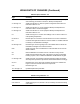
HIGHLIGHTS OF CHANGES Effective April, 2004 Rev. 4.0 Page Summary Cover Updated revision number and date. Deleted certification data. P-3 through P-14 Added foreign language versions of “Safety Instructions for the Wiring and Installation of this Apparatus”. 1-1 Revised Warning. Revised para. 1-2a to include LOI and Model 375 communicator. All IB references to HART Model 275 changed to read “HART Model 275/375”. 1-2 Revised Figure 1-1 to include Oxymitter 4000 remote electronics.
HIGHLIGHTS OF CHANGES (Continued) Effective April, 2004 Rev. 4.0 Page Summary 3-5 Revised para. 3-3a to correct mA signal level values. Moved power up and remaining procedures to Section 5, Startup and Operation. 4-1 through 4-5 Added new Section 4 to discuss system configuration instructions for instruments with an LOI. 5-1 through 5-4 Added new Section 5 to cover equipment Startup and Operation for instruments with a membrane keypad.
Instruction Manual Hazardous Area Oxymitter 4000 IB-106-340C Rev. 4.1 July 2004 TABLE OF CONTENTS PREFACE............................................................................................................................1 Definitions ............................................................................................................................1 Safety Instructions ...............................................................................................................
Instruction Manual IB-106-340C Rev. 4.1 July 2004 6-0 Hazardous Area Oxymitter 4000 6-1 6-2 6-3 6-4 6-5 6-6 6-7 6-8 6-9 STARTUP AND OPERATION OF HAZARDOUS AREA OXYMITTER 4000 WITH LOI......................................................................................................................... 6-1 Power Up ......................................................................................................................... 6-1 Start Up Oxymitter 4000 Calibration.............................
Instruction Manual Hazardous Area Oxymitter 4000 IB-106-340C Rev. 4.1 July 2004 LIST OF ILLUSTRATIONS Figure 1-1. Figure 1-2. Figure 1-3. Figure 1-4. Figure 1-5. Figure 1-6. Figure 1-7. Figure 1-8. Figure 1-9. Figure 1-10. Figure 1-11. Figure 2-1. Figure 2-2. Figure 2-3. Figure 2-4. Figure 2-5. Figure 2-6. Figure 2-7. Figure 2-8. Figure 2-9. Typical System Package .......................................................................................
Instruction Manual IB-106-340C Rev. 4.1 July 2004 Figure 8-10. Figure 8-11. Figure 8-12. Figure 8-13. Figure 8-14. Figure 8-15. Figure 8-16. Figure 8-17. Figure 8-18. Figure 9-1. Figure 9-2. Figure 9-3. Figure 9-4. Figure 9-5. Figure 9-6. Figure 9-7. Figure 9-8. Figure 9-9. Figure 9-10. Figure 9-11. Figure 11-1. Figure 11-2. Hazardous Area Oxymitter 4000 Fault 8, Low Heater Temp ................................................................................... 8-12 Fault 9, High Heater Temp .............
Instruction Manual IB-106-340C Rev. 4.1 July 2004 Hazardous Area Oxymitter 4000 PREFACE The purpose of this manual is to provide information concerning the components, functions, installation and maintenance of the Oxymitter 4000 Hazardous Area Oxygen Transmitter. Some sections may describe equipment not used in your configuration. The user should become thoroughly familiar with the operation of this module before operating it. Read this instruction manual completely.
Instruction Manual IB-106-340C Rev. 4.1 July 2004 Hazardous Area Oxymitter 4000 IMPORTANT SAFETY INSTRUCTIONS FOR THE WIRING AND INSTALLATION OF THIS APPARATUS The following safety instructions apply specifically to all EU member states. They should be strictly adhered to in order to assure compliance with the Low Voltage Directive. NonEU states should also comply with the following unless superseded by local or National Standards. 1.
Instruction Manual Hazardous Area Oxymitter 4000 IB-106-340C Rev. 4.1 July 2004 BELANGRIJK Veiligheidsvoorschriften voor de aansluiting en installatie van dit toestel. De hierna volgende veiligheidsvoorschriften zijn vooral bedoeld voor de EU lidstaten. Hier moet aan gehouden worden om de onderworpenheid aan de Laag Spannings Richtlijn (Low Voltage Directive) te verzekeren.
Instruction Manual IB-106-340C Rev. 4.1 July 2004 Hazardous Area Oxymitter 4000 VIGTIGT Sikkerhedsinstruktion for tilslutning og installering af dette udstyr. Følgende sikkerhedsinstruktioner gælder specifikt i alle EU-medlemslande. Instruktionerne skal nøje følges for overholdelse af Lavsspændingsdirektivet og bør også følges i ikke EU-lande medmindre andet er specificeret af lokale eller nationale standarder. 1.
Instruction Manual Hazardous Area Oxymitter 4000 IB-106-340C Rev. 4.1 July 2004 BELANGRIJK Veiligheidsinstructies voor de bedrading en installatie van dit apparaat. Voor alle EU lidstaten zijn de volgende veiligheidsinstructies van toepassing. Om aan de geldende richtlijnen voor laagspanning te voldoen dient men zich hieraan strikt te houden. Ook niet EU lidstaten dienen zich aan het volgende te houden, tenzij de lokale wetgeving anders voorschrijft. 1.
Instruction Manual IB-106-340C Rev. 4.1 July 2004 Hazardous Area Oxymitter 4000 TÄRKEÄÄ Turvallisuusohje, jota on noudatettava tämän laitteen asentamisessa ja kaapeloinnissa. Seuraavat ohjeet pätevät erityisesti EU:n jäsenvaltioissa. Niitä täytyy ehdottomasti noudattaa jotta täytettäisiin EU:n matalajännitedirektiivin (Low Voltage Directive) yhteensopivuus. Myös EU:hun kuulumattomien valtioiden tulee nou-dattaa tätä ohjetta, elleivät kansalliset standardit estä sitä. 1.
Instruction Manual Hazardous Area Oxymitter 4000 IB-106-340C Rev. 4.1 July 2004 IMPORTANT Consignes de sécurité concernant le raccordement et l’installation de cet appareil. Les consignes de sécurité ci-dessous s’adressent particulièrement à tous les états membres de la communauté européenne. Elles doivent être strictement appliquées afin de satisfaire aux directives concernant la basse tension.
Instruction Manual IB-106-340C Rev. 4.1 July 2004 Hazardous Area Oxymitter 4000 Wichtig Sicherheitshinweise für den Anschluß und die Installation dieser Geräte. Die folgenden Sicherheitshinweise sind in allen Mitgliederstaaten der europäischen Gemeinschaft gültig. Sie müssen strickt eingehalten werden, um der Niederspannungsrichtlinie zu genügen. Nichtmitgliedsstaaten der europäischen Gemeinschaft sollten die national gültigen Normen und Richtlinien einhalten. 1.
Instruction Manual Hazardous Area Oxymitter 4000 IB-106-340C Rev. 4.1 July 2004 IMPORTANTE Norme di sicurezza per il cablaggio e l’installazione dello strumento. Le seguenti norme di sicurezza si applicano specificatamente agli stati membri dell’Unione Europea, la cui stretta osservanza è richiesta per garantire conformità alla Direttiva del Basso Voltaggio. Esse si applicano anche agli stati non appartenenti all’Unione Europea, salvo quanto disposto dalle vigenti normative locali o nazionali. 1.
Instruction Manual IB-106-340C Rev. 4.1 July 2004 Hazardous Area Oxymitter 4000 VIKTIG Sikkerhetsinstruks for tilkobling og installasjon av dette utstyret. Følgende sikkerhetsinstruksjoner gjelder spesifikt alle EU medlemsland og land med i EØS-avtalen. Instruksjonene skal følges nøye slik at installasjonen blir i henhold til lavspenningsdirektivet. Den bør også følges i andre land, med mindre annet er spesifisert av lokale- eller nasjonale standarder. 1.
Instruction Manual Hazardous Area Oxymitter 4000 IB-106-340C Rev. 4.1 July 2004 IMPORTANTE Instruções de segurança para ligação e instalação deste aparelho. As seguintes instruções de segurança aplicam-se especificamente a todos os estados membros da UE. Devem ser observadas rigidamente por forma a garantir o cumprimento da Directiva sobre Baixa Tensão.
Instruction Manual IB-106-340C Rev. 4.1 July 2004 Hazardous Area Oxymitter 4000 IMPORTANTE Instrucciones de seguridad para el montaje y cableado de este aparato. Las siguientes instrucciones de seguridad , son de aplicacion especifica a todos los miembros de la UE y se adjuntaran para cumplir la normativa europea de baja tension. 1. Se deben preveer conexiones a tierra del equipo, tanto externa como internamente, en aquellos terminales previstos al efecto. 2.
Instruction Manual Hazardous Area Oxymitter 4000 IB-106-340C Rev. 4.1 July 2004 VIKTIGT Säkerhetsföreskrifter för kablage och installation av denna apparat. Följande säkerhetsföreskrifter är tillämpliga för samtliga EU-medlemsländer. De skall följas i varje avseende för att överensstämma med Lågspännings direktivet. Icke EU medlemsländer skall också följa nedanstående punkter, såvida de inte övergrips av lokala eller nationella föreskrifter. 1.
Instruction Manual IB-106-340C Rev. 4.1 July 2004 Hazardous Area Oxymitter 4000 P-14 Rosemount Analytical Inc.
Instruction Manual Hazardous Area Oxymitter 4000 IB-106-340C Rev. 4.1 July 2004 CERAMIC FIBER PRODUCTS MATERIAL SAFETY DATA SHEET JULY 1, 1996 SECTION I. IDENTIFICATION PRODUCT NAME Ceramic Fiber Heaters, Molded Insulation Modules and Ceramic Fiber Radiant Heater Panels. CHEMICAL FAMILY Vitreous Aluminosilicate Fibers with Silicon Dioxide. CHEMICAL NAME N.A. CHEMICAL FORMULA N.A.
Instruction Manual IB-106-340C Rev. 4.1 July 2004 Hazardous Area Oxymitter 4000 SECTION II. PHYSICAL DATA APPEARANCE AND ODOR Cream to white colored fiber shapes. With or without optional white to gray granular surface coating and/or optional black surface coating. SPECIFIC WEIGHT: 12-25 lb./cubic foot BOILING POINT: N.A. VOLATILES (% BY WT.): N.A. WATER SOLUBILITY: N.A. SECTION III. HAZARDOUS INGREDIENTS MATERIAL, QUANTITY, AND THRESHOLD/EXPOSURE LIMIT VALUES Aluminosilicate (vitreous) 99+ % CAS.
Instruction Manual Hazardous Area Oxymitter 4000 IB-106-340C Rev. 4.1 July 2004 SECTION V. HEALTH HAZARD DATA THRESHOLD LIMIT VALUE (See Section III) EFFECTS OF OVER EXPOSURE EYE Avoid contact with eyes. Slightly to moderately irritating. Abrasive action may cause damage to outer surface of eye. INHALATION May cause respiratory tract irritation.
Instruction Manual IB-106-340C Rev. 4.1 July 2004 Hazardous Area Oxymitter 4000 TOXICOLOGY A number of studies on the health effects of inhalation exposure of rats and hamsters are available. Rats were exposed to RCF in a series of life-time nose-only inhalation studies. The animals were exposed to 30, 16, 9, and 3 mg/m3, which corresponds with approximately 200, 150, 75, and 25 fibers/cc.
Instruction Manual Hazardous Area Oxymitter 4000 IB-106-340C Rev. 4.1 July 2004 SECTION VII. SPILL OR LEAK PROCEDURES STEPS TO BE TAKEN IF MATERIAL IS RELEASED OR SPILLED Where possible, use vacuum suction with HEPA filters to clean up spilled material. Use dust suppressant where sweeping if necessary. Avoid clean up procedure which may result in water pollution. (Observe Special Protection Information Section VIII.
Instruction Manual IB-106-340C Rev. 4.1 July 2004 Hazardous Area Oxymitter 4000 SECTION IX. SPECIAL PRECAUTIONS PRECAUTIONS TO BE TAKEN IN HANDLING AND STORING General cleanliness should be followed. The Toxicology data indicate that ceramic fiber should be handled with caution. The handling practices described in this MSDS must be strictly followed.
Instruction Manual Hazardous Area Oxymitter 4000 IB-106-340C Rev. 4.1 July 2004 Insulation surface should be lightly sprayed with water before removal to suppress airborne dust. As water evaporates during removal, additional water should be sprayed on surfaces as needed. Only enough water should be sprayed to suppress dust so that water does not run onto the floor of the work area. To aid the wetting process, a surfactant can be used.
Instruction Manual IB-106-340C Rev. 4.1 July 2004 Hazardous Area Oxymitter 4000 GENERAL PRECAUTIONS FOR HANDLING AND STORING HIGH PRESSURE GAS CYLINDERS Edited from selected paragraphs of the Compressed Gas Association’s “Handbook of Compressed Gases” published in 1981 Compressed Gas Association 1235 Jefferson Davis Highway Arlington, Virginia 22202 Used by Permission 1. Never drop cylinders or permit them to strike each other violently. 2.
Instruction Manual IB-106-340C Rev. 4.1 July 2004 Hazardous Area Oxymitter 4000 SECTION 1 DESCRIPTION AND SPECIFICATIONS 1-1 COMPONENT CHECKLIST OF TYPICAL SYSTEM (PACKAGE CONTENTS) A typical Rosemount Hazardous Area Oxymitter 4000 Oxygen Transmitter should contain the items shown in Figure 1-1. Record the part number, serial number, and order number for each component of your system in the table located on the first page of this manual.
Instruction Manual IB-106-340C Rev. 4.1 July 2004 Hazardous Area Oxymitter 4000 2 1 8 7 3 MAN 4275A00 English October 1994 Communicator HART 4 o FISHER-ROSEMOUNTTM 5 6 1. 2. 3. 4. 5. 6. 7. 8.
Instruction Manual IB-106-340C Rev. 4.1 July 2004 Hazardous Area Oxymitter 4000 When the cell is at operating temperature and there are unequal oxygen concentrations across the cell, oxygen ions will travel from the high oxygen partial pressure side to the low oxygen partial pressure side of the cell. The resulting logarithmic output voltage is approximately 50 mV per decade. The output is proportional to the inverse logarithm of the oxygen concentration.
Instruction Manual IB-106-340C Rev. 4.1 July 2004 For systems with one or two Hazardous Area Oxymitter 4000 units per combustion process, an optional remote mounted SPS 4000 Single Probe Autocalibration Sequencer can be used with each Hazardous Area Oxymitter 4000 to provide automatic calibration gas sequencing.
Instruction Manual IB-106-340C Rev. 4.1 July 2004 Hazardous Area Oxymitter 4000 5. Field replaceable cell, heater, thermocouple, diffuser, and PC boards. 6. The Hazardous Area Oxymitter 4000 is constructed of rugged 316L stainless steel for all wetted parts. 7. The electronics is adaptable for line voltages from 90-250 VAC; therefore, no configuration is necessary. 8. The Hazardous Area Oxymitter 4000 membrane keypad is available in five languages: English, French, German, Italian, and Spanish. 9.
Instruction Manual IB-106-340C Rev. 4.1 July 2004 Hazardous Area Oxymitter 4000 f. (d) Optional IMPS 4000. The Programmable Logic Controller (PLC) in the IMPS 4000 provides fault indications using flashing LEDs and LCD display messages. Refer to the IMPS 4000 Intelligent Multiprobe Test Gas Sequencer manual for more information. System Considerations Prior to installing your Hazardous Area Oxymitter 4000, make sure you have all the components necessary to make the system installation.
Instruction Manual IB-106-340C Rev. 4.
Instruction Manual IB-106-340C Rev. 4.
Instruction Manual IB-106-340C Rev. 4.1 July 2004 Hazardous Area Oxymitter 4000 A source of instrument air is optional at the Hazardous Area Oxymitter 4000 for reference air use. Since the unit can be equipped with an in-place calibration feature, provisions can be made to permanently connect calibration gas bottles to the Hazardous Area Oxymitter 4000. If the calibration gas bottles will be permanently connected, a check valve is required next to the calibration fittings on the integral electronics.
Instruction Manual IB-106-340C Rev. 4.1 July 2004 1-6 Hazardous Area Oxymitter 4000 PROBE OPTIONS a. Flame Arrestor Ceramic Diffusion Assembly The flame arrestor ceramic diffusion assembly, Figure 1-9, includes a set of baffles between the cell and the stack gases. This keeps 816°C (1500°F) cell temperatures from igniting unburned fuel in the stack. The ceramic diffusion assembly is also available with a dust seal for use with the abrasive shield assembly. 36220006 Figure 1-10.
Instruction Manual IB-106-340C Rev. 4.1 July 2004 Hazardous Area Oxymitter 4000 2 .187 1 .187 B A o 15 3.584 3.554 o 90 ON INSIDE BREAK FOR SMOOTH ROUNDED EDGE ON BOTH ENDS OF CHAMFER A .45 MIN .187 B 125 6.00 SKIN CUT FACE FOR 90 o VIEW B VIEW A o 22.5 0.75 THRU 4 PLS, EQ SP ON 4.75 B.C. NOTES: 1 WELD ON BOTH SIDES WITH EXPANDING CHILL BLOCK. 2 BEFORE WELDING, BUTT ITEM 2 WITH ITEM 1 AS SHOWN. .745 DIA ON A 7.50 DIA B.C. (REF) .755 Figure 1-11.
Instruction Manual IB-106-340C Rev. 4.1 July 2004 1-7 SPECIFICATIONS O2 Range: Standard............................................. Accuracy ............................................ System Response to Calibration Gas Temperature Limits: Process .............................................. Electronics Housing ........................... Electronics Package .......................... Local Operator Interface ................... Probe Lengths............................................
Instruction Manual IB-106-340C Rev. 4.1 July 2004 Hazardous Area Oxymitter 4000 Power Requirements: Probe Heater...................................... Electronics.......................................... Maximum ........................................... 175 W nominal 10 W nominal 500 W Fisher-Rosemount has satisfied all obligations coming from the European legislation to harmonize the product requirements in Europe. 1-8 HAZARDOUS AREA CERTIFICATIONS a.
Instruction Manual IB-106-340C Rev. 4.1 July 2004 Hazardous Area Oxymitter 4000 Table 1-1. Product Matrix OXT4C OXYMITTER 4000 - EXPLOSION PROOF - IN SITU OXYGEN TRANSMITTER Explosion Proof Oxygen Transmitter - Instruction Book Code 1 2 3 4 5 6 7 8 Sensing Probe Type with Flame Arrestor Ceramic Diffusion Element Probe (ANSI 3 in. 150 lbs) Snubber Diffusion Element (ANSI 3 in. 150 lbs) Ceramic Diffusion Element Probe (DIN 2527) - 1/4 in. Tube Fittings Snubber Diffusion Element (DIN 2527) - 1/4 in.
Instruction Manual IB-106-340C Rev. 4.1 July 2004 Hazardous Area Oxymitter 4000 Table 1-1.
Instruction Manual IB-106-340C Rev. 4.1 July 2004 Hazardous Area Oxymitter 4000 Table 1-2. Calibration Components Part Number Description 1A99119G01 Two disposable calibration gas bottles — 0.4% and 8% O2, balance nitrogen — 550 liters each* 1A99119G02 Two pressure regulators for calibration gas bottles 1A99119G03 Bottle rack *Calibration gas bottles cannot be shipped via airfreight.
Instruction Manual IB-106-340C Rev. 4.1 July 2004 Hazardous Area Oxymitter 4000 SECTION 2 INSTALLATION 2 NOTE The Hazardous Area Oxymitter 4000 and probe abrasive shield are heavy. Use proper lifting and carrying procedures to avoid personal injury. Install all protective equipment covers and safety ground leads after installation. Failure to install covers and ground leads could result in serious injury or death. 2-1 MECHANICAL INSTALLATION a. Selecting Location 1.
18 (.71) 19 (.75) 152.4 (6.00) HOLE DIA (4) HOLES EQ SP ON BC 170 (6.69) 210 (8.25) 190 (7.5) FLANGE DIA BOTTOM VIEW 343 (13.5) DIM "B" REMOVAL ENVELOPE T DIN CI R CU 305 (12) 500 VA 5 Amps IG HT WH E N CI R CU VE ATM OS I O PL WA RN I NG - SPH EX - EXTERNAL EARTH REF. GAS 6 FT 3 FT 18 IN. PROBE DIM "B" 803 (31.6) 1448 (57.0) 2174 (85.6) DIM "A" 460 (18.1) 917 (36.1) 1831 (72.
Instruction Manual IB-106-340C Rev. 4.1 July 2004 Hazardous Area Oxymitter 4000 REMOTE ELECTRONICS WITH MEMBRANE KEYPAD AND BLIND COVER 62.0 (2.44) DIA. REMOTE ELECTRONICS WITH LOI AND WINDOW COVER 2 NOTE: ALL DIMENSIONS ARE IN MILLIMETERS WITH INCHES IN PARENTHESES. 56.0 (2.21) 164.6 (6.48) 189.8 (7.47) 246.9 (9.72) 84.6 (3.33) 140.2 (5.52) WALL MOUNT CONFIGURATION 93.5 (3.68) PIPE MOUNT CONFIGURATION 66.5 (2.62) 37270013 Figure 2-2.
DIFFUSER/DUST SEAL ASSY 6 FT 1762 (69.4) 2287 (90.0) 1367 (53.8) 843 (33.2) 912 (35.9) 18 IN 3 FT DIM "B" 387 (15.3) IG HT WHE N C CI R U VE ATM OS I O PL WA RN I NG - SPH EX - IT 3/4 NPT ELECTRICAL CONNECTION CAL GAS* REF AIR ANSI 1/4 IN. TUBE DIN 1/4 IN. TUBE JIS 6 mm TUBE *ADD CHECK VALVE IN CAL GAS LINE CAL. GAS 343 (13.50) T DIM "A" TABLE 4 ABRASIVE SHIELD -3D39003 DIN JIS ANSI FLANGE 235 235 229 FLANGE (9.25) (9.25) (9.00) DIA 24 19 19 HOLE (0.75) DIA (0.94) (0.
Rosemount Analytical Inc. A Division of Emerson Process Management B C B C 22.5o 190 (7.48) M20 x 2.5 100 (3.94) 235 (9.25) DIN MOUNTING PLATE FOR HAZARDOUS AREA OXYMITTER 4000 WITH ABRASIVE SHIELD A A 191 (7.50) "D" DIA B.C. CROSSHATCHED AREA IN 4 CORNERS MAY BE USED TO PROVIDE ADDITIONAL HOLES FOR FIELD BOLTING OF PLATE TO OUTSIDE WALL SURFACE. 0.625-11 121 (4.75) 229 (9.00) ANSI "C" THREAD "B" DIA "A" DIMENSIONS MM (in.) ABRASIVE SHIELD FLANGE O.D.
Instruction Manual IB-106-340C Rev. 4.1 July 2004 Hazardous Area Oxymitter 4000 INSTALLATION FOR METAL WALL STACK OR DUCT CONSTRUCTION INSTALLATION FOR MASONRY WALL STACK CONSTRUCTION ABRASIVE SHIELD MOUNTING 13 (0.50) 13 (0.50) BOLT MOUNTING PLATE TO OUTSIDE WALL SURFACE FIELD WELD PIPE TO MOUNTING PLATE 95 (3.
Instruction Manual IB-106-340C Rev. 4.1 July 2004 Hazardous Area Oxymitter 4000 4. If using the optional ceramic diffusion element, the vee deflector must be correctly oriented. Before inserting the Hazardous Area Oxymitter 4000, check the direction of flow of the gas in the duct. Orient the vee deflector so the apex points upstream toward the flow (Figure 2-6). This may be done by loosening the setscrews and rotating the vee deflector to the desired position. Retighten the setscrews. 5.
Instruction Manual IB-106-340C Rev. 4.1 July 2004 Hazardous Area Oxymitter 4000 - IVE - KEE IG HT WHE N CI R CU VE ATM O OS I PL WARN I NG - SPH EX - AL E ER LOGIC I/O, 4-20 mA SIGNAL IT LINE VOLTAGE P T DRIP LOOP IN CAL. GAS REPLACE INSULATION AFTER INSTALLING HAZARDOUS AREA OXYMITTER 4000 INSULATION MOUNTING PLATE STACK OR DUCT METAL WALL 26310010 Figure 2-7. Installation with Drip Loop and Insulation Removal 2-2 c.
Instruction Manual Hazardous Area Oxymitter 4000 To meet the Safety Requirements of IEC 1010 (EC requirement), and ensure safe operation of this equipment, connection to the main electrical power supply must be made through a circuit breaker (min 10 A) which will disconnect all current-carrying conductors during a fault situation. This circuit breaker should also include a mechanically operated isolating switch.
Instruction Manual IB-106-340C Rev. 4.
Instruction Manual Hazardous Area Oxymitter 4000 2-3 ELECTRICAL INSTALLATION (FOR HAZARDOUS AREA OXYMITTER 4000 WITH REMOTE ELECTRONICS) All wiring must conform to local and national codes. Disconnect and lock out power before connecting the unit to the power supply. Install all protective equipment covers and safety ground leads after installation. Failure to install covers and ground leads could result in serious injury or death.
Instruction Manual IB-106-340C Rev. 4.1 July 2004 Hazardous Area Oxymitter 4000 GRN RED BLU WHT BRN - + + - BRN TYPE K THERMOCOUPLE SIGNAL OXYGEN SIGNAL HEATER POWER (BELOW COVER) PROBE TERMINAL BLOCK GRN/YEL or GRN REMOTE ELECTRONICS GROUND LUGS CALIBRATION HANDSHAKE/ LOGIC I/O 4-20 mA SIGNAL LINE VOLTAGE - AC AC N L1 TO ELECTRONICS YEL RED 3 4 5 6 T/C BLK ORN 2 BLK GRN 1 2 7 8 HTR TERMINAL BLOCK GROUND LUGS BLK (BRN) (HAZ.) WHT (BLU) G.P.
Instruction Manual IB-106-340C Rev. 4.1 July 2004 Hazardous Area Oxymitter 4000 RED BLU GRN WHT BRN - + - + PROBE BRN TYPE K THERMOCOUPLE SIGNAL OXYGEN SIGNAL HEATER POWER (BELOW COVER) TERMINAL BLOCK GRN/YEL or GRN REMOTE ELECTRONICS 2 GROUND LUGS CALIBRATION HANDSHAKE/ LOGIC I/O 4-20 mA SIGNAL LINE VOLTAGE - AC AC N L1 TO ELECTRONICS YEL RED 2 3 4 5 6 BLK ORN 1 BLK GRN 7 8 T/C HTR BLK (BRN) (HAZ.) WHT (BLU) G.P.
Instruction Manual IB-106-340C Rev. 4.1 July 2004 Hazardous Area Oxymitter 4000 1. Remove cover (17, Figure 9-4) from the junction box (24). Connect the electronics end of the interconnecting cable (30) to the “FROM PROBE” side of the terminal block (Figure 2-10). If using an IMPS 4000 or an SPS 4000, install it in a non-hazardous, explosivefree environment. 2. Calibration Handshake/Logic I/O.
Instruction Manual IB-106-340C Rev. 4.1 July 2004 Hazardous Area Oxymitter 4000 NOTE: DIMENSIONS ARE IN MILLIMETERS WITH INCHES IN PARENTHESES. ALL PIPING SPECIFIED IN U.S. STANDARDS. 0.125-27 NPT OUTLET 1 79.25 (3.12) MAX 3 2 SCHEMATIC HOOKUP FOR REFERENCE AIR SUPPLY TO HAZARDOUS AREA OXYMITTER 4000 PROBE HEAD. 2 57.15 (2.250) Rosemount Analytical Inc. Orrville, OH 44667-0901 800-433-6076 SMART FAMILY HARTTM R TM OUTLET 122.17 (4.81) 30.22 (1.19) FLOW SET POINT KNOB 254 REF (10.0) 0.
Instruction Manual IB-106-340C Rev. 4.1 July 2004 Hazardous Area Oxymitter 4000 ! NOTE Upon completing installation, make sure that the Hazardous Area Oxymitter 4000 is turned on and operating prior to firing up the combustion process. Damage can result from having a cold Hazardous Area Oxymitter 4000 exposed to the process gases. During outages, and if possible, leave all Hazardous Area Oxymitter 4000 units running to prevent condensation and premature aging from thermal cycling.
Instruction Manual IB-106-340C Rev. 4.1 July 2004 Hazardous Area Oxymitter 4000 SECTION 3 CONFIGURATION OF HAZARDOUS AREA OXYMITTER 4000 WITH MEMBRANE KEYPAD b. Verify Terminal Block Wiring 1. Remove screw (18, Figure 9-3 or Figure 9-4), cover lock (19), and captive washer (20) that secure cover (17) on left side of housing (11). Remove the cover. Install all protective equipment covers and safety ground leads before equipment startup.
Instruction Manual IB-106-340C Rev. 4.1 July 2004 Hazardous Area Oxymitter 4000 c. Verify Hazardous Area Oxymitter 4000 Configuration Hazardous Area Oxymitter 4000. The defaults cannot be changed via HART/AMS unless the switch is in the HART position. Placing SW2, position 1 in the LOCAL position forces the O2 range to the setting of position 2. The position 1 switch must be placed in the LOCAL position or changes in SW2, position 2 will have no effect.
Instruction Manual IB-106-340C Rev. 4.1 July 2004 Hazardous Area Oxymitter 4000 output reverts to the process gas. When a calibration has been initiated, the value at TP5 and TP6 is the %O2 seen by the cell. Oxygen levels, as seen on the multimeter, are: 1. Access TP5 and TP6 next to the membrane keypad. Attach a multimeter across TP5 and TP6. The calibration and process gases can now be monitored. Pressing the INC or DEC once will cause the output to switch from the process gas to the calibration gas.
Instruction Manual IB-106-340C Rev. 4.1 July 2004 Hazardous Area Oxymitter 4000 The HART option is not protected by energy limiting barriers. It must not be interfaced from within the hazardous area. The 4-20 mA cables should be routed and the connections made outside the hazardous area. Note that this is the case even when using the intrinsically safe version of the handheld communicator.
Instruction Manual Hazardous Area Oxymitter 4000 3-3 RECOMMENDED CONFIGURATION a. 4-20 mA Signal Upon Critical Alarm Rosemount recommends that the factory default be utilized. The 4-20 mA signal will go to the 3.5 mA level upon any critical alarm which will cause the O2 reading to be unusable. Customer can also select 21.6 mA as the failure setting if normal operations cause O2 readings to go below the zero % O2 (3.5 mA) level.
Instruction Manual IB-106-340C Rev. 4.1 July 2004 Hazardous Area Oxymitter 4000 3-6 Rosemount Analytical Inc.
Instruction Manual IB-106-340C Rev. 4.1 July 2004 Hazardous Area Oxymitter 4000 SECTION 4 CONFIGURATION OF HAZARDOUS AREA OXYMITTER 4000 WITH LOI b. Verify Terminal Block Wiring 4-1 Install all protective equipment covers and safety ground leads before equipment startup. Failure to install covers and ground leads could result in serious injury or death. 1. Remove screw (18, Figure 9-3 or Figure 9-4), cover lock (19), and captive washer (20) that secure cover (17) on left side of housing (11).
Instruction Manual IB-106-340C Rev. 4.1 July 2004 c. Verify Hazardous Area Oxymitter 4000 Configuration Located on the microprocessor board are two switches that configure Hazardous Area Oxymitter 4000 outputs (Figure 4-2). To access these switches, the LOI module must be removed. SW1 determines if the 4-20 mA signal is internally or externally powered. SW2 determines: The HART option is not protected by energy limiting barriers. It must not be interfaced from within the hazardous area.
Instruction Manual IB-106-340C Rev. 4.1 July 2004 Hazardous Area Oxymitter 4000 f. Once the cell is up to operating temperature, the O2 percentage can be read: 1. To access TP5 and TP6 under the LOI module (Figure 4-2), power down the Oxymitter 4000 and remove the LOI module. Attach alligator leads from a multimeter across TP5 and TP6 (Figure 3-2). Install the LOI module and power up the Oxymitter 4000. Allow time for the cell to reach operating temperature.
Instruction Manual IB-106-340C Rev. 4.1 July 2004 Hazardous Area Oxymitter 4000 The HART option is not protected by energy limiting barriers. It must not be interfaced from within the hazardous area. The 4-20 mA cables should be routed and the connections made outside the hazardous area. Note that this is the case even when using the intrinsically safe version of the handheld communicator.
Instruction Manual Hazardous Area Oxymitter 4000 4-3 RECOMMENDED CONFIGURATION a. 4-20 mA Signal Upon Critical Alarm Rosemount recommends that the factory default be utilized. The 4-20 mA signal will go to the 3.5 mA level upon any critical alarm which will cause the O2 reading to be unusable. Customer can also select 21.6 mA as the failure setting if normal operations cause O2 readings to go below the zero % O2 (3.5 mA) level.
Instruction Manual IB-106-340C Rev. 4.1 July 2004 Hazardous Area Oxymitter 4000 4-6 Rosemount Analytical Inc.
Instruction Manual IB-106-340C Rev. 4.1 July 2004 Hazardous Area Oxymitter 4000 SECTION 5 STARTUP AND OPERATION OF HAZARDOUS AREA OXYMITTER 4000 WITH MEMBRANE KEYPAD 5-1 b. Operating Display POWER UP The ramp cycle turns into a cycle where the diagnostic LEDs light in sequence from the top to the bottom, one at a time. After the bottom LED turns on, the sequence starts again at the top with the HEATER T/C LED (Figure 5-1). a.
Instruction Manual IB-106-340C Rev. 4.1 July 2004 Hazardous Area Oxymitter 4000 3. TEST POINTS. Test points 1 through 6 allow you to monitor with a multimeter: the heater thermocouple, the O2 cell millivolt value, and the process O2. d. Keypad The five membrane keys on the membrane keypad are only used during calibration to adjust the high and low gas and to initiate the calibration sequence (Figure 5-2).
Instruction Manual IB-106-340C Rev. 4.1 July 2004 Hazardous Area Oxymitter 4000 4. CAL LED. The CAL LED is on steady or flashing during calibration. Further information is available in Section 9, MAINTENANCE AND SERVICE. 8.0% O2 = 8.0 volts DC 5. Keys. 0.4% O2 = 0.4 volts DC Oxygen levels, as seen on the multimeter, are: (b) CAL. The CAL key can: (a) INC and DEC. The INC and DEC keys are used to set the values of the calibration gases. Attach a multimeter across TP5 and TP6.
Instruction Manual IB-106-340C Rev. 4.1 July 2004 Hazardous Area Oxymitter 4000 5-4 Rosemount Analytical Inc.
Instruction Manual IB-106-340C Rev. 4.1 July 2004 Hazardous Area Oxymitter 4000 SECTION 6 STARTUP AND OPERATION OF HAZARDOUS AREA OXYMITTER 4000 WITH LOI 6-1 POWER UP a. Startup Display When power is applied to the probe, the cell heater turns on. It takes approximately one half hour for the cell to heat to operating temperature. This condition is indicated by a “warm up” display on the LOI (Figure 6-1). This message will continue to display until the cell is up to operating temperature. b.
Instruction Manual IB-106-340C Rev. 4.1 July 2004 SELECTION ARROW TOUCH CONFIRMATION LED Hazardous Area Oxymitter 4000 b. Lockout The Local Operator Interface (LOI) has a lockout feature that prevents nuisance actuation by someone brushing against the glass window, raindrops, dirt, insects, etc. This lockout mode is automatically established when no buttons are pushed for 30 seconds (default). This countdown to lockout is configurable.
Instruction Manual IB-106-340C Rev. 4.1 July 2004 Hazardous Area Oxymitter 4000 6-5 LOI MENU TREE Menu items in normal text display information, only. Menu Items in italics permit data entry. Menu items in bold text are procedures. This LOI menu for the Oxymitter 4000 is shown in Figure 6-4. This menu tree is specific to the Oxymitter 4000. The menu tree will assist in navigating the LOI.
Instruction Manual IB-106-340C Rev. 4.1 July 2004 Hazardous Area Oxymitter 4000 (CONTINUED FROM SHEET 1) O2 Gas 1 O2 Gas 2 O2-Reset Vals O2 Out Tracks O2 Cal Intervl O2-Next Cal Gas Time Purge Time Auto Calib? Calib Setup Analog Input/Output Digital SYSTEM Parameters Software Status _____% _____% Yes/No Yes/No ____H ____H ___Sec. ___Sec. Yes/No O2 Type O2 Range O2 Alarm Level Do O2 Trim _______ ______% _____mA Logic IO Mode See Table 4-1 Low O2 Alarm See para.
Instruction Manual IB-106-340C Rev. 4.1 July 2004 Hazardous Area Oxymitter 4000 7. Gas Time – How long should each cal gas flow. Factory default is 300 seconds, but the user may want to vary this depending upon the length of calibration gas tubing runs. 8. Purge Time – Used if the O2 output is selected to hold the last value during calibration. After the second cal gas is removed, how long until the sensor comes back to the normal process reading, and the 4-20 mA signal can be released. 9.
Instruction Manual IB-106-340C Rev. 4.1 July 2004 Hazardous Area Oxymitter 4000 d. SYSTEM/Status (c) Board Temp – The temperature inside the Oxymitter electronics housing (85°C is the max.). 1. Alarms – Diagnostic alarms. See Section 8, TROUBLESHOOTING. (d) Board Temp Max. – This is the maximum temperature that the electronics has experienced over time. 2.
Instruction Manual IB-106-340C Rev. 4.1 July 2004 Hazardous Area Oxymitter 4000 6-8 OXYMITTER 4000 TEST POINTS b. TP3 and TP4 monitor the heater thermocouple. Refer to Figure 6-6. System test points are located on the board below the LOI module. Test points 1 through 6 allow you to monitor with a multimeter: the heater thermocouple, the O2 cell millivolt, and the process O2. a. TP1 and TP2 monitor the oxygen cell millivolt output which equates to the percentage of oxygen present. c.
Instruction Manual IB-106-340C Rev. 4.1 July 2004 Hazardous Area Oxymitter 4000 6-8 Rosemount Analytical Inc.
Instruction Manual IB-106-340C Rev. 4.1 July 2004 Hazardous Area Oxymitter 4000 SECTION 7 HART/AMS The HART Communicator accomplishes its task using a frequency shift keying (FSK) technique. With the use of FSK, high-frequency digital communication signals are superimposed on the Hazardous Area Oxymitter 4000’s 4-20 mA current loop. The HART communicator does not disturb the 4-20 mA signal, since no net energy is added to the loop. The HART option is not protected by energy limiting barriers.
Instruction Manual IB-106-340C Rev. 4.1 July 2004 Hazardous Area Oxymitter 4000 b. Method 2, For Load Resistance < 250 Ohms a. Method 1, For Load Resistance ≥ 250 Ohms Refer to Figure 7-1 and the following steps to connect the HART Communicator to a signal line 250 ohms or more of load resistance. Refer to Figure 7-2 and the following steps to connect the HART Communicator to a signal line with less than 250 ohms load resistance. Explosions can result in death or serious injury.
Instruction Manual IB-106-340C Rev. 4.1 July 2004 Hazardous Area Oxymitter 4000 AC L1 AC N RL < 250Ω + - 4-20 mA SIGNAL LINE + 4-20 - TERMINAL BLOCK ANALOG OUTPUT DEVICE LOOP CONNECTORS SERIAL PORT & BATTERY CHARGER MUST NOT BE USED IN LOOP CONNECTORS 250 OHM LOAD RESISTOR (NOTE) USE INTERFACE 00275 0013 ONLY SERIAL PORT HAZARDOUS AREAS HART COMMUNICATOR HART COMMUNICATOR REAR PANEL NOTE: THE SIGNAL LOOP MUST BE BROKEN TO INSERT THE OPTIONAL 250 OHM LOAD RESISTOR. 23230002 Figure 7-2.
Instruction Manual IB-106-340C Rev. 4.1 July 2004 7-5 Hazardous Area Oxymitter 4000 7-6 LOGIC I/O CONFIGURATIONS The Hazardous Area Oxymitter 4000 logic I/O output can be configured for ten different modes through HART/AMS. The factory default condition is Mode 5. A list of possible configurations appear in Table 7-1. HART/AMS MENU TREE FOR HAZARDOUS AREA OXYMITTER 4000 APPLICATIONS This section consists of a menu tree for the HART Communicator.
Instruction Manual IB-106-340C Rev. 4.1 July 2004 Hazardous Area Oxymitter 4000 VIEW FLD DEV VARS PROCESS VARIABLES VIEW OUTPUT VARS VIEW FLD DEV mV O2 value O2 cell temp CJ temp VIEW PV-Aout PV is PV O2 value PV % rnge PV AO VIEW SV SV is Cold Junct SV __ mV VIEW TV TV is Cell TV __ mV VIEW 4V 4V is Cell TC 4V __ mV Cell mV Cell TC mV CJ mV Status Group 1 DEVICE SETUP PV PV AO PV LRV PV URV STATUS Status Group 2 Cell Temp Low Cell Temp High Cell Open High Cell Imp. CK.ER - EEPROM Cal.
Instruction Manual IB-106-340C Rev. 4.
Instruction Manual IB-106-340C Rev. 4.
Instruction Manual IB-106-340C Rev. 4.1 July 2004 7-7 Hazardous Area Oxymitter 4000 HART COMMUNICATOR O2 CAL METHOD the O2 CALIBRATE screen and select menu item 2, O2 CAL STATUS, to view menu item 1, CAL-STATE; menu item 2, TIMEREMAIN; and menu item 3, PRESENT O2, as the calibration status updates. Use the following procedure to perform a calibration using the HART Communicator. If necessary, use the menu tree in Figure 7-3 (sheet 1 of 3) for reference. f.
Instruction Manual Hazardous Area Oxymitter 4000 7-8 IB-106-340C Rev. 4.1 July 2004 DEFINING A TIMED CALIBRATION VIA HART a. From the DEVICE SETUP screen, select DETAILED SETUP. Use the following procedure to specify a time interval (in hours) at which the Hazardous Area Oxymitter 4000 will be automatically calibrated. If necessary, use the menu tree in Figure 7-3 (sheet 2 of 3) for reference. b. From the DETAILED SETUP screen, select O2 CALIBRATION. c.
Instruction Manual IB-106-340C Rev. 4.1 July 2004 Hazardous Area Oxymitter 4000 7-10 Rosemount Analytical Inc.
Instruction Manual IB-106-340C Rev. 4.1 July 2004 Hazardous Area Oxymitter 4000 SECTION 8 TROUBLESHOOTING 8-1 OVERVIEW the difference between the process O2% and the reference O2% inside the probe (20.95% O2 ambient air). While the Hazardous Area Oxymitter 4000 electronics provides a significant number of diagnostic alarms to assist in troubleshooting potential problems, it’s good to place these alarms in perspective with respect to the instrument’s operating principles: b.
Instruction Manual IB-106-340C Rev. 4.1 July 2004 Hazardous Area Oxymitter 4000 work loose. Before troubleshooting the system, ensure all ICs are fully seated. d. When flowing calibration gasses, the raw cell millivolt value at test points 1 and 2 should represent the levels on the chart in Figure 8-1. Note that the raw cell millivolt value increases logarithmically as the O2 concentration decreases. Install all protective equipment covers and safety ground leads after troubleshooting.
Instruction Manual IB-106-340C Rev. 4.1 July 2004 Hazardous Area Oxymitter 4000 8-4 ALARM CONTACTS 2. Additional IMPS 4000 Alarm Contacts. (a) One contact per IMPS 4000 for “low calibration gas flowing”. a. If autocalibration is not utilized, a common bi-directional logic contact is provided for any of the diagnostic alarms listed in Table 8-1. The assignment of alarms which can actuate this contact can be modified to one of seven additional groupings (mode 0 through mode 7) listed in Table 7-1.
Instruction Manual IB-106-340C Rev. 4.1 July 2004 Hazardous Area Oxymitter 4000 Table 8-1.
Instruction Manual Hazardous Area Oxymitter 4000 IB-106-340C Rev. 4.1 July 2004 a.
Instruction Manual IB-106-340C Rev. 4.1 July 2004 Hazardous Area Oxymitter 4000 b.
Instruction Manual Hazardous Area Oxymitter 4000 IB-106-340C Rev. 4.1 July 2004 c.
Instruction Manual IB-106-340C Rev. 4.1 July 2004 Hazardous Area Oxymitter 4000 d. HEATER T/C HEATER O2 CELL CALIBRATION Membrane Keypad. When Fault 4 is detected, the HEATER T/C LED flashes four times, pauses for three seconds, and repeats (Figure 8-6). SW2 ON DIAGNOSTIC ALARMS 1. Call the factory for assistance.
Instruction Manual IB-106-340C Rev. 4.1 July 2004 Hazardous Area Oxymitter 4000 e. Fault 5, Open Heater SW2 ON HEATER T/C HEATER O2 CELL CALIBRATION DIAGNOSTIC ALARMS Figure 8-7 shows the electronic assembly for a Hazardous Area Oxymitter 4000 with a membrane keypad (upper view) and a Hazardous Area Oxymitter 4000 with an LOI (lower view).
Instruction Manual IB-106-340C Rev. 4.1 July 2004 Hazardous Area Oxymitter 4000 f. HEATER T/C HEATER O2 CELL CALIBRATION Figure 8-8 shows the electronic assembly for a Hazardous Area Oxymitter 4000 with a membrane keypad (upper view) and a Hazardous Area Oxymitter 4000 with an LOI (lower view).
Instruction Manual Hazardous Area Oxymitter 4000 IB-106-340C Rev. 4.1 July 2004 g. Fault 7, High Case Temp HEATER T/C HEATER O2 CELL CALIBRATION SW2 ON DIAGNOSTIC ALARMS Figure 8-9 shows the electronic assembly for a Hazardous Area Oxymitter 4000 with a membrane keypad (upper view) and a Hazardous Area Oxymitter 4000 with an LOI (lower view).
Instruction Manual IB-106-340C Rev. 4.1 July 2004 Hazardous Area Oxymitter 4000 h. Fault 8, Low Heater Temp SW2 ON HEATER T/C HEATER O2 CELL CALIBRATION DIAGNOSTIC ALARMS Figure 8-10 shows the electronic assembly for a Hazardous Area Oxymitter 4000 with a membrane keypad (upper view) and a Hazardous Area Oxymitter 4000 with an LOI (lower view).
Instruction Manual IB-106-340C Rev. 4.1 July 2004 Hazardous Area Oxymitter 4000 i. Figure 8-11 shows the electronic assembly for a Hazardous Area Oxymitter 4000 with a membrane keypad (upper view) and a Hazardous Area Oxymitter 4000 with an LOI (lower view). SW2 ON HEATER T/C HEATER O2 CELL CALIBRATION DIAGNOSTIC ALARMS CALIBRATION RECOMMENDED TEST POINTS INC INC HIGH GAS LOW GAS DEC DEC J1 TP1 TP2 TP3 TP4 RED YEL GRN ORG O2 CELL mV + O2 CELL mv HEATER T/C + HEATER T/C - Membrane Keypad.
Instruction Manual IB-106-340C Rev. 4.1 July 2004 Hazardous Area Oxymitter 4000 j.
Instruction Manual IB-106-340C Rev. 4.1 July 2004 Hazardous Area Oxymitter 4000 k. Fault 11, Bad Cell HEATER T/C HEATER O2 CELL CALIBRATION SW2 ON DIAGNOSTIC ALARMS Figure 8-13 shows the electronic assembly for a Hazardous Area Oxymitter 4000 with a membrane keypad (upper view) and a Hazardous Area Oxymitter 4000 with an LOI (lower view).
Instruction Manual IB-106-340C Rev. 4.1 July 2004 Hazardous Area Oxymitter 4000 l. HEATER T/C HEATER O2 CELL CALIBRATION Figure 8-14 shows the electronic assembly for a Hazardous Area Oxymitter 4000 with a membrane keypad (upper view) and a Hazardous Area Oxymitter 4000 with an LOI (lower view). SW2 ON DIAGNOSTIC ALARMS CALIBRATION RECOMMENDED INC INC HIGH GAS LOW GAS DEC DEC J1 TP1 TP2 TP3 TP4 RED YEL GRN ORG TEST POINTS O2 CELL mV + O2 CELL mv HEATER T/C + HEATER T/C - Membrane Keypad.
Instruction Manual IB-106-340C Rev. 4.1 July 2004 Hazardous Area Oxymitter 4000 m. Fault 13, Invalid Slope SW2 ON HEATER T/C HEATER O2 CELL CALIBRATION DIAGNOSTIC ALARMS Figure 8-15 shows the electronic assembly for a Hazardous Area Oxymitter 4000 with a membrane keypad (upper view) and a Hazardous Area Oxymitter 4000 with an LOI (lower view).
Instruction Manual IB-106-340C Rev. 4.1 July 2004 Hazardous Area Oxymitter 4000 n. Fault 14, Invalid Constant SW2 ON HEATER T/C HEATER O2 CELL CALIBRATION DIAGNOSTIC ALARMS Figure 8-16 shows the electronic assembly for a Hazardous Area Oxymitter 4000 with a membrane keypad (upper view) and a Hazardous Area Oxymitter 4000 with an LOI (lower view).
Instruction Manual Hazardous Area Oxymitter 4000 IB-106-340C Rev. 4.1 July 2004 o. Fault 15, Last Calibration Failed SW2 ON HEATER T/C HEATER O2 CELL CALIBRATION DIAGNOSTIC ALARMS Figure 8-17 shows the electronic assembly for a Hazardous Area Oxymitter 4000 with a membrane keypad (upper view) and a Hazardous Area Oxymitter 4000 with an LOI (lower view).
Instruction Manual IB-106-340C Rev. 4.1 July 2004 8-6 HAZARDOUS AREA OXYMITTER 4000 PASSES CALIBRATION, BUT STILL READS INCORRECTLY Hazardous Area Oxymitter 4000 CORRUGATED SEAL REFERENCE AIR EXHAUST PORT PROBE HEAD There are a few fault conditions where no alarm indication is present and the probe passes calibration, but the O2 reading may still be incorrect: a. Probe passes calibration, but still appears to read high. 1.
Instruction Manual Hazardous Area Oxymitter 4000 3. Always note the time it takes for the cell to recover to the normal process value after the cal gas is removed. As the diffuser plugs, this recovery time will get longer and longer. Use the Calibration Record form provided in this manual. Can I calibrate a badly plugged diffuser? 1. It may not be possible to immediately replace a plugged diffuser while the process is on line. IB-106-340C Rev. 4.1 July 2004 2.
Instruction Manual IB-106-340C Rev. 4.1 July 2004 Hazardous Area Oxymitter 4000 Calibration Record For Rosemount Analytical In Situ O2 Probe Probe Serial Number: Probe Tag Number: Probe Location: Date Placed Into Service: Date Notes: Responseinitial Responsefinal 9-0 Slope Constant Impedance Responseinitial Responsefinal When the second calibration gas is turned off, note the number of seconds required for the O2 value to begin migrating back to the process value.
Instruction Manual IB-106-340C Rev. 4.1 July 2004 Hazardous Area Oxymitter 4000 SECTION 9 MAINTENANCE AND SERVICE 9-1 OVERVIEW This section identifies the calibration methods available and provides the procedures to maintain and service the Hazardous Area Oxymitter 4000. When working on this equipment on the laboratory bench, be aware that the Hazardous Area Oxymitter 4000, probe tube, and flame arrestor hub can be hot [up to 300°C (572°F)] in the region of the probe heater.
Instruction Manual IB-106-340C Rev. 4.1 July 2004 The HART option is not protected by energy limiting barriers. It must not be interfaced from within the hazardous area. The 4-20 mA cables should be routed and the connections made outside the hazardous area. Note that this is the case even when using the intrinsically safe version of the handheld communicator. Do not install an IMPS 4000 or SPS 4000 within the hazardous area.
Instruction Manual IB-106-340C Rev. 4.1 July 2004 Hazardous Area Oxymitter 4000 2. Semi-Automatic Calibration. Semiautomatic calibrations only require operator initiation. However, the calibration gases must be permanently piped to the Hazardous Area Oxymitter 4000, an SPS 4000 or IMPS 4000 must be installed to sequence the gases, and the logic I/O must be set to mode 8 or 9 via HART/AMS to allow the sequencer and the Hazardous Area Oxymitter 4000 to communicate.
Instruction Manual IB-106-340C Rev. 4.
Instruction Manual IB-106-340C Rev. 4.1 July 2004 Hazardous Area Oxymitter 4000 calibration). If the slope or the constant is out of specification, a diagnostic alarm LED will be flashing. The diagnostic alarm will remain active until the purge cycle is over. If the three pattern flash occurs without a diagnostic alarm, the calibration gases could be the same or the calibration gas was not turned on. A flashing CAL LED indicates the calibration is done.
Instruction Manual IB-106-340C Rev. 4.1 July 2004 4. Touch the Enter arrow to start the Gas 2 flow. The timer is activated and the LOI displays: Flow Gas 2xxxxs Read Gas 2xxxxs Done Gas 2 Stop Gas Hit E when ready 5. Remove the second calibration gas and cap off the calibration gas port. Then, touch the Enter arrow to indicate completion. The timer is activated and the LOI displays: Purgexxxxs The default purge time is three minutes.
Instruction Manual IB-106-340C Rev. 4.1 July 2004 Hazardous Area Oxymitter 4000 9-4 HAZARDOUS AREA OXYMITTER 4000 REPAIR Each of the following procedures details how to remove and replace a specific component of the Hazardous Area Oxymitter 4000. It is recommended that the Hazardous Area Oxymitter 4000 be removed from the stack for all service activities. The unit should be allowed to cool and be taken to a clean work area. Failure to comply may cause severe burns.
Instruction Manual IB-106-340C Rev. 4.1 July 2004 Hazardous Area Oxymitter 4000 16 15 12 13 Note: The Electronic Assembly, item 2, consists of items 3 through 10. 11 17 14 1. 1A. 2. 17A 3. 4. 18 4A. 19 5. 20 6. 7. 8. 9. 10. 11. 12. 13. 14. 15. 16. 17. 17A. 18. 19. 20. 21. 22. 23. 24. 25. 26.
Instruction Manual IB-106-340C Rev. 4.
Instruction Manual IB-106-340C Rev. 4.1 July 2004 Hazardous Area Oxymitter 4000 NOTE Recalibration is required whenever electronic cards or sensing cell is replaced. b. Replacement of Entire Electronics (with Housing) – Hazardous Area Oxymitter 4000 with Integral Electronics. 1. Follow the instructions in paragraph 9-4a to remove the Hazardous Area Oxymitter 4000 probe from the stack or duct.
Instruction Manual Hazardous Area Oxymitter 4000 POWER SUPPLY BOARD IB-106-340C Rev. 4.1 July 2004 10. Reconnect the J1 connector to the microprocessor board (Figure 9-5). Ensure the connector is secure. 11. Tighten the three captive screws (9, Figure 9-3 or Figure 9-4) in the top of the microprocessor board (5). J8 37270022 Figure 9-6. J8 Connector 3. Loosen the three captive screws (9, Figure 9-3 or Figure 9-4). Slide electronic assembly (2) partially out of housing (11). 4. See Figure 9-6.
Instruction Manual IB-106-340C Rev. 4.1 July 2004 Opening the electronic housing will cause the loss of ALL hazardous permits. Opening the electronics housing in a hazardous area may cause an explosion resulting in loss of property, severe personal injury, or death. It may be required to get a hot work permit from your company safety officer before opening the electronic housing. Hazardous Area Oxymitter 4000 POWER SUPPLY BOARD FUSE e. Fuse Replacement See Figure 9-7. 1.
Instruction Manual Hazardous Area Oxymitter 4000 15. Replace right housing cover (1, Figure 9-3); make sure it is tight. Secure the cover using captive washer (20), cover lock (19), and screw (18). 16. Install and tighten cover (1); make sure it is tight. Secure the cover using captive washer (20), cover lock (19), and screw (18).
Instruction Manual IB-106-340C Rev. 4.1 July 2004 Hazardous Area Oxymitter 4000 WIRE LOOP V-DEFLECTOR CERAMIC DIFFUSER ASSEMBLY CERAMIC SUPPORT ROD CELL FLANGE HEATER 27540007 Figure 9-8. Heater Strut Assembly 6. Remove tube clamps (33). Carefully pull the CAL and REF gas silicon tubes (34) from the CAL and REF gas ports. 7. Remove gas port fittings (29) from the CAL, REF, and VENT ports. 8. See Figure 9-8.
Instruction Manual IB-106-340C Rev. 4.1 July 2004 Hazardous Area Oxymitter 4000 When working on this equipment on the laboratory bench, be aware that the Hazardous Area Oxymitter 4000, probe tube, and flame arrestor hub can be hot [up to 300°C (572°F)] in the region of the probe heater. h. Cell Replacement This paragraph covers O2 cell replacement. Do not attempt to replace the cell until all other possibilities for poor performance have been considered.
Instruction Manual IB-106-340C Rev. 4.1 July 2004 Hazardous Area Oxymitter 4000 installed. Disconnect the orange cell wire at the probe electronics end of the strut by cutting the wire. Withdraw the cell with the wire still attached. M5-0.8 x 5 mm LOCKING SET SCREW (USE 2.5 mm HEX KEY) THREADED PROBE FLANGE SPANNER WRENCH 5. Remove entire electronics per paragraph 9-4b, steps 2 and 3.
Instruction Manual Hazardous Area Oxymitter 4000 12. If previously removed, install the entire electronics per paragraph 9-4b, steps 4 and 5. 13. Follow the instructions in paragraph 2-1b to install the Hazardous Area Oxymitter 4000 into the stack or duct. If there is an abrasive shield in the stack, make sure the dust seal gaskets are in place as they enter the 15° reducing cone. i. Ceramic Diffusion Element Replacement NOTE This procedure applies to the ceramic diffuser element only. 1.
Instruction Manual IB-106-340C Rev. 4.1 July 2004 diffusion element into seat. Do not get any cement on upper part of ceramic diffusion element. Ensure complete penetration of cement around 3 grooves in hub. Cement should extrude from opposite hole. Wipe excess material back into holes and wipe top fillet of cement to form a uniform fillet. (A Q-Tip is useful for this.) Clean any excess cement from hub with water. (j) Allow filter to dry at room temperature overnight or 1 to 2 hours at 93°C (200°F).
Instruction Manual IB-106-340C Rev. 4.1 July 2004 Hazardous Area Oxymitter 4000 SECTION 10 RETURN OF MATERIAL 10-1 If factory repair of defective equipment is required, proceed as follows: a. Secure a return authorization number from a Rosemount Analytical Sales Office or representative before returning the equipment. Equipment must be returned with complete identification in accordance with Rosemount instructions or it will not be accepted.
Instruction Manual IB-106-340C Rev. 4.1 July 2004 Hazardous Area Oxymitter 4000 10-2 Return of Material Rosemount Analytical Inc.
Instruction Manual IB-106-340C Rev. 4.1 July 2004 Hazardous Area Oxymitter 4000 SECTION 11 REPLACEMENT PARTS Table 11-1. Replacement Parts for Probe Figure and Index No.
Instruction Manual IB-106-340C Rev. 4.1 July 2004 Hazardous Area Oxymitter 4000 Table 11-1. Replacement Parts for Probe (Continued) Figure and Index No.
Instruction Manual IB-106-340C Rev. 4.1 July 2004 Hazardous Area Oxymitter 4000 Table 11-1. Replacement Parts for Probe (Continued) Figure and Index No.
Instruction Manual IB-106-340C Rev. 4.1 July 2004 Hazardous Area Oxymitter 4000 Table 11-2. Replacement Parts for Electronics Figure and Index No.
Instruction Manual IB-106-340C Rev. 4.1 July 2004 Hazardous Area Oxymitter 4000 SECTION 12 OPTIONAL ACCESSORIES 12 HART HANDHELD 375 COMMUNICATOR The HART Handheld 375 Communicator is an interface device that provides a common communication link to HART-compatible instruments, such as the Oxymitter 4000. HART Communications Protocol permits all the information available from the Oxymitter 4000’s electronics to be transmitted over standard 4-20 mA signal wires.
Instruction Manual IB-106-340C Rev. 4.1 July 2004 Hazardous Area Oxymitter 4000 IMPS 4000 INTELLIGENT MULTIPROBE TEST GAS SEQUENCER The IMPS 4000 Intelligent Multiprobe Test Gas Sequencer is housed within an IP56 (NEMA 4X) enclosure and has the intelligence to provide calibration gas sequencing of up to four Hazardous Area Oxymitter 4000 units to accommodate automatic and semi-automatic calibration routines.
Instruction Manual Hazardous Area Oxymitter 4000 IB-106-340C Rev. 4.1 July 2004 O2 CALIBRATION GAS Rosemount Analytical’s O2 Calibration Gas and Service Kits have been carefully designed to provide a more convenient and fully portable means of testing, calibrating, and servicing Rosemount Analytical’s oxygen analyzers. These lightweight, disposable gas cylinders eliminate the need to rent gas bottles. 12 For more information, call Rosemount Analytical at 1-800-433-6076.
Instruction Manual IB-106-340C Rev. 4.1 July 2004 Hazardous Area Oxymitter 4000 12-4 Rosemount Analytical Inc.
Instruction Manual IB-106-340C Rev. 4.1 July 2004 Hazardous Area Oxymitter 4000 SECTION 13 INDEX This index is an alphabetized listing of parts, terms, and procedures having to do with the Hazardous Area Oxymitter. Every item listed in this index refers to a location in the manual by one or more page numbers.
Instruction Manual IB-106-340C Rev. 4.
WARRANTY Rosemount warrants that the equipment manufactured and sold by it will, upon shipment, be free of defects in workmanship or material. Should any failure to conform to this warranty become apparent during a period of one year after the date of shipment, Rosemount shall, upon prompt written notice from the purchaser, correct such nonconformity by repair or replacement, F.O.B. factory of the defective part or parts.
Instruction Manual IB-106-340C Rev. 4.1 July 2004 Hazardous Area Oxymitter 4000 Hazardous Area Oxymitter 4000 Part no. Serial no. Order no. Emerson Process Management Rosemount Analytical Inc. Process Analytic Division 1201 N. Main St. Orrville, OH 44667-0901 T (330) 682-9010 F (330) 684-4434 E gas.csc@emersonprocess.com Fisher-Rosemount GmbH & Co. Industriestrasse 1 63594 Hasselroth Germany T 49-6055-884 0 F 49-6055-884209 ASIA - PACIFIC Fisher-Rosemount Singapore Private Ltd.