
- Emerson Electric Co. Oxygen Equipment User's Manual


Instruction Manual
IB-106-340C Rev. 4.1
July 2004
Rosemount Analytical Inc. A Division of Emerson Process Management HART/AMS 7-1
Hazardous Area Oxymitter 4000
SECTION 7
HART/AMS
The HART option is not protected by
energy limiting barriers. It must not be
interfaced from within the hazardous
area. The 4-20 mA cables should be
routed and the connections made out-
side the hazardous area. Note that this
is the case even when using the in-
trinsically safe version of the handheld
communicator.
7-1 OVERVIEW
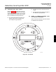
The HART Communicator is a handheld com-
munications interface device. It provides a
common communications link to all microproc-
essor-based instruments that are HART com-
patible. The handheld communicator contains
an 8 x 21 character liquid crystal display (LCD)
and 25 keys. A pocket-sized manual, included
with the HART Communicator, details the spe-
cific functions of all the keys.
To interface with the Hazardous Area Oxymitter
4000, the HART Communicator requires a ter-
mination point along the 4-20 mA current loop
and a minimum load resistance of 250 ohms
between the communicator and the power
supply.
The HART Communicator accomplishes its task
using a frequency shift keying (FSK) technique.
With the use of FSK, high-frequency digital
communication signals are superimposed on
the Hazardous Area Oxymitter 4000’s 4-20 mA
current loop. The HART communicator does not
disturb the 4-20 mA signal, since no net energy
is added to the loop.
The HART Communicator may be interfaced
with a personal computer (PC), providing that
special software has been installed. To connect
the HART Communicator to a PC, an interface
adapter is required. Refer to the proper HART
Communicator documentation in regard to the
PC interface option.
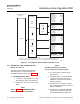
7-2 HART COMMUNICATOR SIGNAL LINE
CONNECTIONS
The HART Communicator can connect to the
Hazardous Area Oxymitter 4000’s analog output
signal line at any wiring termination in the 4-20
mA current loop. There are two methods of
connecting the HART Communicator to the
signal line. For applications in which the signal
line has a load resistance of 250 ohms or more,
refer to method 1. For applications in which the
signal line load resistance is less than 250
ohms, refer to method 2.
7