
- Emerson Electric Co. Oxygen Equipment User's Manual


Instruction Manual
IB-106-340C Rev. 4.1
July 2004
Rosemount Analytical Inc. A Division of Emerson Process Management Troubleshooting 8-3
Hazardous Area Oxymitter 4000
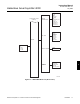
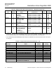
8-4 ALARM CONTACTS
a. If autocalibration is not utilized, a common
bi-directional logic contact is provided for
any of the diagnostic alarms listed in Table
8-1. The assignment of alarms which can
actuate this contact can be modified to one
of seven additional groupings (mode 0
through mode 7) listed in Table 7-1.
The logic contact is self-powered, +5 VDC,
with a 340 ohm series resistance. An inter-
posing relay will be required if this contact is
to be utilized to annunciate a higher voltage
device, such as a light or horn. An inter-
posing relay may also be required for cer-
tain DCS input cards.
A Potter & Brumfield R10S-E1Y1-J1.0K 3.2
mA DC or an equal interposing relay will be
mounted where the contact wires terminate
in the control/relay room.
b. If autocalibration systems are utilized, the
bi-directional logic contact is utilized as a
“hand-shake” signal between the autocali-
bration system (SPS 4000 or IMPS 4000)
and is unavailable for alarming purposes.
The following additional contacts are pro-
vided through the autocalibration systems:
1. SPS 4000 and IMPS 4000, 1-4 probes.
(a) One contact closure per probe
from the control room to the SPS
4000 or IMPS 4000 for “calibration
initiate”.
(b) One contact output per probe from
the SPS 4000 or IMPS 4000 to the
control room for “in calibration”
notification.
(c) One contact output per probe from
the SPS 4000 or IMPS 4000 to the
control room for “calibration failed”
notification. (Includes output from
pressure switch indicating “cal gas
bottles empty”).
2. Additional IMPS 4000 Alarm Contacts.
(a) One contact per IMPS 4000 for
“low calibration gas flowing”.
(b) One contact per IMPS 4000 for
“high calibration gas flowing”.
NOTE
The 4-20 mA signal can be configured
to respond normally during any cali-
bration, or can be configured to hold
the last O
2
value upon the initiation of
calibration. Factory default is for the
4-20 mA signal to operate normally
throughout calibration.
NOTE
Holding the last O
2
value may be useful
if several probes are being averaged
for the purpose of automatic control.
Unless several probes are being aver-
aged, always place any control loops
using the O
2
signal into manual prior to
calibrating.
8-5 IDENTIFYING AND CORRECTING ALARM
INDICATIONS
For a Hazardous Area Oxymitter 4000 with a
membrane keypad, faults are indicated by four
diagnostic, or unit, alarm LEDs. A pattern of
repeating blinks define the problem. A con-
densed table of the errors and the correspond-
ing blink codes can be found on the inside right
cover of the electronics housing. Table 8-1 also
identifies the blink code and fault status of each
LED as well as the output of the 4-20 mA signal
line and a fault number that corresponds to the
troubleshooting instructions provided in this
section.
For a Hazardous Area Oxymitter 4000 with the
optional LOI, alarm messages are displayed on
the LOI display window when the alarm status
display is accessed via the LOI menu. A listing
of the alarm/fault messages and the related fault
status descriptions and fault numbers are
shown in Table 8-2.
8